
Summary of Contents for Starlite MK5
-
Page 1: User/ Service Manual
Starlite Mk 5 User/ Service Manual Version 1.2 STARLITE Mk5 User Manual Version 1.2... -
Page 2: Copyright
Stardraw and Stardraw Professional are registered trademarks of Starlite Systems Technology Limited. Starlite is a trade name of Starlite Systems Technology Limited. Starlite fully acknowledges all other trademarks and trade names mentioned in this manual and disclaim any propriety interest in them or the companies owning them. Distributor Lane Lighting Ltd. -
Page 3: Important Handling Notes
Although the Starlite Mk5 is designed to withstand constant use in all entertainment environments, some care must be taken in the handling of the unit, especially when it is being packed/unpacked and when it is being rigged in its working position. -
Page 4: Notes
Notes STARLITE Mk5 User Manual Version 1.2... -
Page 5: Table Of Contents
_________________________________________________________ 14 UICK EFERENCE UIDE ________________________________________________________ 15 NPACKING THE TARLITE Save the shipping materials _____________________________________________________ 15 Flightcase (Roadcase) Design ___________________________________________________ 15 Returning the unit to Starlite ____________________________________________________ 15 ________________________________________________________ 15 LECTRICAL ONNECTIONS ___________________________________________________________ 15 OWER EQUIREMENTS ___________________________________________________________ 16 AFETY NSTRUCTIONS... - Page 6 Remove and replace colour wheel Dichroic Filters __________________________________ 46 Remove and install gobos in the optional Static Wheel. _______________________________ 47 MK5 A _____________________________________________________ 48 TARLITE DJUSTMENTS Adjusting the Decoder card reference voltage. ______________________________________ 48 STARLITE Mk5 User Manual Version 1.2...
- Page 7 Technical Support_____________________________________________________________ 54 Fault-Finding (cont.) __________________________________________________________ 55 ________________________________________ 56 ASIC OOLS AND QUIPMENT EQUIRED ____________________________________________________ 57 PARES AND PTIONAL XTRAS DMX A ________________________________________________________ 58 AMPLE DDRESSES ________________________________________________________ 59 ARRANTY NFORMATION ._________________________________________________ 60 OTES OMMENTS AND ROBLEMS STARLITE Mk5 User Manual Version 1.2...
-
Page 8: Declaration Of Conformity
In addition to being tested to the above generic International EMC, LVD and Safety Directives/ Standards, every Starlite Mk 5 is tested for electrical safety before leaving the factory . It is highly recommended that you re-apply these tests at intervals, as directed by your local safety authority, to ensure the safety of the Unit(s) and the people and place(s) in which the Unit(s) are being used. -
Page 9: Introduction
Thank you for purchasing the Starlite MK5 moving light, manufactured by Starlite Systems Technology Limited. The Starlite MK5 is the most advanced moving yoke instrument that can be purchased in the world today and is ideally suited for theatrical applications, stage, studio, concert touring and night clubs. -
Page 10: Glossary
Alternating Current. High Tension. An electric current that constantly reverses its High voltage. In the Starlite Mk 5 this relates to the direction. The rate of direction change is the connections from the ignitor to the HMI lamp. frequency (Hz). -
Page 11: Starlite Mk5 Description And Features
Modular design allows for module swapping, upgrading, easy servicing and cleaning. Easy internal access and fast Lamp change (thru safety interlocked door) Four carrying handles and multiple hanging points Rugged construction and durable exterior epoxy paint finish STARLITE Mk5 User Manual Version 1.2... -
Page 12: Caution And Warning Symbols
♦ For safety reasons and correct operation, the unit(s) must be earthed! ♦ The Starlite Mk5 lamp will produce ultraviolet radiation in use. Exposure to unshielded lamp will result in skin and eye burns. The unit is fitted with an interlock system, which will extinguish the lamp if the lamp-housing door is opened. -
Page 13: Cautions
♦ Only transport the unit in its original packaging or a properly constructed flightcase. ♦ The Starlite Mk5 contains no user serviceable parts other than consumable part replacement and normal preventative maintenance. Servicing must be carried out by authorised and suitably trained or instructed personnel. -
Page 14: Quick Reference Guide
This Quick Reference Guide is intended only as a reminder of the main elements concerning the use of a Starlite Mk5. It is not intended as a substitute for reading the whole, or parts of, the manual. Please ensure that you have read and completely understood the manual before attempting to operate the unit. -
Page 15: Unpacking The Starlite
Flightcase (Roadcase) Design Any case used for transporting the Starlite Mk 5 must be carefully designed. It must contain strong, semi-rigid supports for the different sections of the unit, enclosed in a rigid outer casing. Ready made flight cases can be obtained through your distributor. -
Page 16: Safety Instructions
(and two of the red LED’s will start flashing) . Then after a further three minutes, the red LED’s will stop flashing, indicating it is safe to switch off the units and disconnect from the power source. (See Status Indicator Panel) STARLITE Mk5 User Manual Version 1.2... -
Page 17: Specifications (Mechanical)
Safety Wire/ Rigging Point 179 mm 50 mm 200 mm 201 mm 50 mm 179 mm Detail of base fixing points (M10 threaded) Detail of base fixing points (M10 threaded) EARLIER MODELS CURRENT MODELS STARLITE Mk5 User Manual Version 1.2... -
Page 18: Rigging The Unit
It is recommended “wrap-over” (half couplers or Cheeseborough) type clamps are used. These are available in pairs, from STARLITE, complete with fixing bolts. Part No.0370/2 An optional base plate, with additional ¼ turn “Camloc” fixing points, is also available, from STARLITE Part No. -
Page 19: Specifications (Electrical)
10 Amp (T) 250 V 20mm or 32mm (1¼”) PLEASE NOTE: Replacement fuses must be of the “T” type (i.e. time delay/slow blow) and of the correct voltage/current rating. Replacement fuses are available from your distributor/Starlite. STARLITE Mk5 User Manual Version 1.2... -
Page 20: Specifications (Environmental Conditions)
5º C (41º F) Relative humidity: Maximum 80% (up to 31º C) 40% (at 40º C) Working environment: Working area Indoor use only Altitude: Maximum 2000 M (6500 ft) IP (Ingress Protection) Rating: IP20 STARLITE Mk5 User Manual Version 1.2... -
Page 21: Control Data Protocol
3 inside a male 5-pin XLR connector. Max. Required DMX Channels: A maximum of 19 DMX Channels are required for a STARLITE Mk5.(The No. of channels is dependent on units configuration) Therefore a maximum of 26 STARLITE Mk 5’s may be controlled from one (DMX) Control Desk output string. -
Page 22: Factory Set Personality
Factory Set Personality The Starlite Mk 5 is despatched with the default personality set (as described below) but this can be altered to any other personality, if the user wishes. This feature is extremely useful when the Starlite Mk 5 is being used along with, or takes the place of, other makes of moving lights. The Starlites can be configured to the personality required, there by reducing programming time. - Page 23 Bump Change Gobo “Indexing” 4 Bump Change Gobo “Indexing” 5 Open White Scroll Change Gobo “Indexing” 1 Scroll Change Gobo “Indexing” 2 Scroll Change Gobo “Indexing” 3 Scroll Change Gobo “Indexing” 4 Scroll Change Gobo “Indexing” 5 STARLITE Mk5 User Manual Version 1.2...
- Page 24 Bump Change Gobo “Indexing” 5 Open White Scroll Change Gobo “Indexing” 1 Scroll Change Gobo “Indexing” 2 Scroll Change Gobo “Indexing ” 3 Scroll Change Gobo “Indexing ” 4 Scroll Change Gobo “Indexing “ 5 STARLITE Mk5 User Manual Version 1.2...
- Page 25 Rotate Slow CW Stop 49.5% Rotate Slow CCW 52.5% Rotate Fast CCW Frost Open(Hard Edged) Closed(Diffused) 100% *Shutter Closed Strobing Slow Strobing fast Open 97.5% Dimmer Closed *(Shutter Blades Close) 0.75% Open 100% Timing(Speed) 100% STARLITE Mk5 User Manual Version 1.2...
-
Page 26: Unit Review
DMX signal is applied, the green LED will extinguish. Status LED’s 1 to 4 show the lamp, interlock and switch states and should not be lit after the lamp has struck or during normal use. For more information, please refer to section ”2 way Switch” STARLITE Mk5 User Manual Version 1.2... -
Page 27: Set The Starlite Mk5 Unit Voltage
Set the Starlite MK5 Unit Voltage The method of setting the unit voltage varies depending on which type of lamp ballast is fitted to the unit. Please refer to the specification label on the base of the unit to determine what type of lamp ballast is in the unit. -
Page 28: Lamp Ballast Voltage/Frequency Selection
Electronic Ballast Version The Switch-Mode Power Supplies fitted to both the 575 W and the 1200 W versions do not require adjustment when used within the specified Voltage/Frequency limits. i.e. 95-130 and 200-250 Volts, 47-65 Hz STARLITE Mk5 User Manual Version 1.2... -
Page 29: The Yoke
¼ turn fastener located thru the “Release” hole and unplugging the fan module (if necessary). When replacing the fan module/card retainer ensure that you re-plug the fan power connector. Recessed ¼ turn fastener on fan unit ¼ turn fasteners Step 1 Step 2 STARLITE Mk5 User Manual Version 1.2... -
Page 30: Fan" Side Of The Head (Current Models)
. It is recommended that you do not disconnect this safety wire unless you cannot get enough access to the head with it in place ¼ turn fasteners STEP 1 STEP 2 ¼ turn fasteners STEP 3 STARLITE Mk5 User Manual Version 1.2... -
Page 31: Open View Of The Head (Fan Side)
Rotating gobo wheel (21) Shutter section (10) Iris (22) Tilt motor assembly (11) Gobo module retaining clip (2 off) (23) Secondary fan retaining clip (12) Head cover retaining clip (2 off per side) (24) Colour wheel STARLITE Mk5 User Manual Version 1.2... -
Page 32: Motherboard" Side Of The Head
¼ turn fasteners Focus unit connector Note: Please take care not to stretch the cable looms that are connected to the motherboard. STARLITE Mk5 User Manual Version 1.2... -
Page 33: Lamp Housing
8) Hold onto the metal frame of the lamp / lens module and ease the module away from its mounting / locating studs by gently pulling backwards. When free, rest the module on the back door. STARLITE Mk5 User Manual Version 1.2... -
Page 34: Lamp Installation (Cont.)
Warning: Whenever you are working on or near the lamp, wear protective eyewear and gloves. An operating unshielded lamp emits ultraviolet and visible radiation, which could damage eyes and skin. STARLITE Mk5 User Manual Version 1.2... -
Page 35: Setting The Dmx Start Address Bcd Switches
Lamp addressing starts from address 1 with address zero reserved for self-test mode. The Starlite Mk5 unit can be addressed with any start address. Each unit requires a maximum of 19 DMX channels depending on the function specification. -
Page 36: Setting The Drive Card Dip Switches
Note: These switches are factory set to the standard personality listed below. 8 Way Binary Personality Switch Edge Connector with locating slot STARLITE Mk 5 DRIVE CARD (Issue 3) Drive Internal DMX Functions Address 8 way DIP switch STARLITE Mk5 User Manual Version 1.2... -
Page 37: Drive Card Address Information
This part of the switch sets the internal DMX address of each drive card in relation to the overall personality of the unit. These are factory set to the default Starlite Mk 5 Personality but they can be altered, allowing the unit to be configured to the personality required. e.g. The same as other moving lights in the system. -
Page 38: Drive Card Motherboard Positions
STARLITE Mk 5 Motherboard (Issue 3) N.B. In current models the head fan and Safety/Interlock connections are combined in one 8-way connector. Please do not attempt to remove the drive cards whilst the unit is powered up. STARLITE Mk5 User Manual Version 1.2... -
Page 39: Unit Review (Cont.)
2 is used to inhibit the lamp strike during testing. The normal status for these switches is as follows: Switch Status Switch 1 Switch 2 Lamp Strike Enabled 2 minute time out Enabled Lamp Strike Enabled 2 minute time-out Disabled Lamp Strike Disabled STARLITE Mk5 User Manual Version 1.2... -
Page 40: Status Led's
During the cool down period with LED’s 4 and 2 flashing, it is not possible to re-strike the unit by applying valid DMX for 3 minutes. If DMX is applied, the unit will re-strike after this 3 minute sequence. STARLITE Mk5 User Manual Version 1.2... -
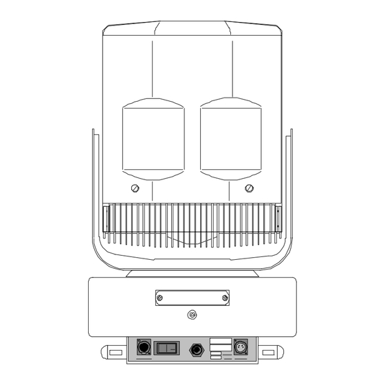
Page 41: Rear (Dc Supply) Side Of Base
BEFORE working in this area. Ignitor PFC capacitors Connections Switch-Mode PSU. (Type varies with model.) In magnetic ballast models, this area also contains the two different frequency taps for the ballast. See “Setting the Starlite Mk5 unit Voltage” STARLITE Mk5 User Manual Version 1.2... -
Page 42: Servicing The Starlite Mk5
Servicing the Starlite MK5 General Maintenance and Cleaning The Starlite MK5 should be cleaned on a regular basis to maintain performance and reliability. As a guide the Starlite MK5 should be cleaned at every lamp change to maintain peak performance. -
Page 43: Removing The Cmy Module
When replacing any of the modules, please ensure the spring wires (at the top and bottom of each module) locate in the grooves cut into the two retaining bars. This ensures the optimum optical alignment of the different modules in the lamp. STARLITE Mk5 User Manual Version 1.2... -
Page 44: Removing The Gobo Module
When replacing any of the modules, please ensure the spring wires (at the top and bottom of each module) locate in the grooves cut into the two retaining bars. This ensures the optimum optical alignment of the different modules in the lamp. STARLITE Mk5 User Manual Version 1.2... -
Page 45: Cleaning Head Modules
When replacing any of the modules, please ensure the spring wires (at the top and bottom of each module) locate in the grooves cut into the two retaining bars. This ensures the optimum optical alignment of the different modules in the lamp. STARLITE Mk5 User Manual Version 1.2... -
Page 46: Replacing Parts
Rear of Colour/Gobo Module Gently push the Once the colour (shown outside fixture for clarity) colour filter filter is clear of towards centre of the edge clips, the wheel tilt up and slide away from wheel. STARLITE Mk5 User Manual Version 1.2... -
Page 47: Remove And Install Gobos In The Optional Static Wheel
Once the gobo has cleared the two edge retaining clips, tilt the gobo away from the edge clips and slide out from under the centre retaining plate. Replace gobos by reversing the above procedure. STARLITE Mk5 User Manual Version 1.2... -
Page 48: Starlite Mk5 Adjustments
DMX address switch Edge connector with locating slot STARLITE Mk5 DECODER CARD (Issue 3) Adjusting the Pan position sensor(Earlier models) This should not require adjustment during normal use. If adjustment is required, first unplug the unit and remove the cover over the main pan ring drive gear to expose the pan drive gear and position sensor. -
Page 49: To Adjust Pan Sensor (Cont.)
“input connector” side of the base. Pan sensor mounted on spring-damped arm. STARLITE Mk5 User Manual Version 1.2... -
Page 50: To Adjust Pan Sensor (Cont.)
The Pan gearbox and clutch assembly is factory set and therefore should not need any adjustment in normal use. If you suspect they need adjustment, please call for Technical Support or refer to a qualified engineer before attempting to make any alterations to the unit. STARLITE Mk5 User Manual Version 1.2... -
Page 51: Adjusting The Tilt Position Sensor
If this plate is removed, care should be taken as the plate is under tension. Slacken all 3 fixing screws and tilt the plate to remove tension before removing the top 2 screws and springs. STARLITE Mk5 User Manual Version 1.2... -
Page 52: Adjusting The Tilt Gearbox
8. Re-assemble unit and reset tilt sensor (if necessary) Second push motor sideways “Flat” headed Motor plate screw mounting screws (and spacers) “Hex” cap head screw First push motor upwards STARLITE Mk5 User Manual Version 1.2... -
Page 53: Adjusting The Pan/Tilt Drive Card Settings
If the drives become too unstable due to incorrect set-up, the fuses for the DC drive circuits will blow. In this event power down the unit and ensure that you complete step 1 above before replacing the fuses and re-powering the unit. STARLITE Mk5 User Manual Version 1.2... -
Page 54: Fault-Finding And Repair
Note 1: It would be helpful if your telephone was close to the area in which you are repairing the unit. Note 2: Often a faxed sketch diagram of the faulty part will help the Starlite engineer solve your problem faster. -
Page 55: Fault-Finding (Cont.)
• • Drive card wrongly Re-address card addressed • • Module miss-plugged Check both ribbon cables connecting module to motherboard. • • Module damaged Replace module • • Unit wrongly addressed Re-address unit • STARLITE Mk5 User Manual Version 1.2... -
Page 56: Basic Tools And Test Equipment Required
Most of the tools listed below should be readily available in any technician’s toolbox, but please note the following points; • All fasteners used in the Starlite Mk 5 are of the standard METRIC type, apart from the exception of the lamp isolating posts which are UNC 8-32 x ¼”. -
Page 57: Spares And Optional Extras
Base cover screws and washers (set of 4) Part No. 0207/4/C PTFE lubricating oil (for rotating gobos) Part No. 0455 Other colour filters, custom gobos and beam effects are available. Please enquire for details. STARLITE Mk5 User Manual Version 1.2... -
Page 58: Sample Dmx Addresses
Sample DMX Addresses The table below gives some sample DMX addresses (starting from channel 1) but the Starlite Mk5 can have any start address so long as there are 18 channels available after the start address. (i.e. 19 channels total) -
Page 59: Warranty Information
Warranty Information Warranty Information Your Starlite MK5 fixture (‘Unit’) is covered by a 365-day parts and labour limited warranty against defects in material and workmanship from the date of purchase subject as follows: 1. It is the owners’ responsibility to provide receipts or invoices for proof of purchase showing date, dealer or distributor. -
Page 60: Notes, Comments And Problems
Notes, Comments and Problems. Please write down any notes, comments or problems you have using your Starlite Mk5 moving lights and send them to us. That way, we can do our best to improve the design and functionality of the unit.
Need help?
Do you have a question about the MK5 and is the answer not in the manual?
Questions and answers