Table of Contents
Advertisement
Advertisement
Table of Contents

Related Manuals for SportsArt Fitness 7100


Summary of Contents for SportsArt Fitness 7100
- Page 1 SportsArt 7100/S7100 Stepper Repair Manual Version1: 12-26-01 Version 2: 10-26-04...
- Page 2 Version 2: Oct. 26, 2004 – Updated to reflect changes in the S7100 stepper. In the spring of 2004, the original 7100 stepper was updated. The display was changed and the product name became S7100. Even though some operational steps may differ due to the display change change, product functions are basically the same, and troubleshooting techniques are the same.
-
Page 3: Table Of Contents
SportsArt 7100/S7100 Stepper Repair Manual – Basic Illustrations Table of Contents Chapter 1. Stepper Basic Illustrations 7100/S7100 1-1-1. Stepper Illustration (Assembled Unit) 1-2-1. Stepper Electronic Component Locations 1-3-1. Stepper Cable Connections 1-4-1. Stepper Display Board Cable Connections 1-5-1. Stepper Drive Board Cable Connections 1-6-1. - Page 4 SportsArt 7100/S7100 Stepper Repair Manual – Operation Table of Contents Chapter 2. Stepper Operation 2-1-1. Stepper Battery Operation (Continued through 2-1-5) 2-2-1. Stepper Generator Operation (Continued through 2-2-2) 2-3-1. Stepper Optic Sensor Signal Flow Chart (Continued through 2-3-2) 2-4-1. Stepper Resistance Operation Flow Chart (Continued through 2-4-3) 2-5-1.
- Page 5 SportsArt 7100/S7100 Stepper Repair Manual – Testing Table of Contents Chapter 3. Stepper Testing 3-1-1. Drive Board Power Component Test (Continued through 3-1-2) 3-2-1. Drive Board Power VCC Voltage Test (Continued through 3-2-4) 3-3-1. Generator Voltage Test at the Drive Board (Continued through 3-3-2) 3-4-1.
-
Page 6: Stepper Basic Illustrations
SportsArt 7100/S7100 Stepper Repair Manual – Basic Illustrations Chapter 1. Stepper Basic Illustrations 7100/S7100 1-1-1. Stepper Illustration (Assembled Unit) 1-2-1. Stepper Electronic Component Locations 1-3-1. Stepper Cable Connections 1-4-1. Stepper Display Board Cable Connections 1-5-1. Stepper Drive Board Cable Connections 1-6-1. -
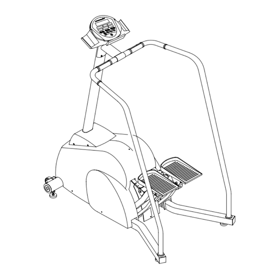
Page 7: Stepper Illustration (Assembled Unit)
SportsArt 7100/S7100 Stepper Repair Manual – Basic Illustrations Stepper Illustration (Assembled Unit) Note: The original 7100 stepper is shown.The display on S7100 is different. 1-1-1... -
Page 8: Stepper Electronic Component Locations
SportsArt 7100/S7100 Stepper Repair Manual – Basic Illustrations Stepper Electronic Component Locations Magnet and Flywheel Display HTR Handlebar Drive Board Generator Battery Optic Sensor 1-2-1... -
Page 9: Stepper Cable Connections
SportsArt 7100/S7100 Stepper Repair Manual – Basic Illustrations Stepper Cable Connections 3 PIN Board Display Board Soft Keys POLAR 3 PIN HR Board Magnet and Generator 2 PIN 2 PIN Flywheel Drive Board FUSE Battery Optic Sensor 3 PIN 1-3-1... -
Page 10: Stepper Display Board Cable Connections
SportsArt 7100/S7100 Stepper Repair Manual – Basic Illustrations Stepper Display Board Cable Connections HTR Board & HTR Handlebar 3 pin POLAR Drive 16 pin cable 3 pin cable HR Board Board Note: S7100 cable connections may differ. Soft Keys CNT3... -
Page 11: Stepper Drive Board Cable Connections
SportsArt 7100/S7100 Stepper Repair Manual – Basic Illustrations Stepper Drive Board Cable Connections Display Board 16 PIN Optic Battery Magnet Generator Sensor 1-5-1... -
Page 12: Stepper Display Board Component Placement
SportsArt 7100/S7100 Stepper Repair Manual – Basic Illustrations Stepper Display Board Component Placement 1-6-1... -
Page 13: Stepper Drive Board Component Placement
SportsArt 7100/S7100 Stepper Repair Manual – Basic Illustrations Stepper Drive Board Component Placement Circuit Protection Note: The latest drive board, V3.1, is not shown here. V3.1 came out 04-12-04. It operates with Optic both 7100 and S7100 displays. Sensor Changing the... -
Page 14: 7100 Stepper Display Overlay
SportsArt 7100/S7100 Stepper Repair Manual – Basic Illustrations 7100 Stepper Display Overlay Note: The S7100 display overlay is different. 1-8-1... -
Page 15: Chapter 2. Stepper Operation
SportsArt 7100/S7100 Stepper Repair Manual – Operation Chapter 2. Stepper Operation 2-1-1. Stepper Battery Operation (Continued through 2-1-5) 2-2-1. Stepper Generator Operation (Continued through 2-2-2) 2-3-1. Stepper Optic Sensor Signal Flow Chart (Continued through 2-3-2) 2-4-1. Stepper Resistance Operation Flow Chart (Continued through 2-4-3) 2-5-1. -
Page 16: Stepper Battery Operation (Continued Through 2-1-5)
SportsArt 7100/S7100 Stepper Repair Manual – Operation Stepper Battery Operation 1. Configuration Display Board Soft Keys ON,OFF Drive Board Battery 2 pin 2-1-1... - Page 17 SportsArt 7100/S7100 Stepper Repair Manual – Operation 2. Battery Operation Order Component Operation Battery 1. When no one is exercising on the stepper, the battery provides the drive board with power, allowing the display to light. Soft Keys 1. If the unit has yet to be turned on, pressing the “ON” key results in a signal that prompts the drive board into action.
- Page 18 SportsArt 7100/S7100 Stepper Repair Manual – Operation Battery Switch Operation 1. Battery Switch Operation Order Component Operation Soft key 1. Press TIME<▼>+LEVEL<▼> to turn off the battery. Display board 1. Display CPU reads the soft key OFF signal. 2. The CPU sends an OFF signal to the drive board.
- Page 19 SportsArt 7100/S7100 Stepper Repair Manual – Operation Battery Off Action – Automatic Shut Off 1. Configuration Display Drive Board 16 PIN VCC, 2. Operation Order Part Operation Display 1. The display board reads the optic sensor signal to distinguish whether the unit is being used.
- Page 20 SportsArt 7100/S7100 Stepper Repair Manual – Operation 3. Procedure Step Operation The display lights up normally. When no one is exercising on the machine, the display TIME window value doesn’t change. After two minutes, the display turns off; display lights extinguish.
-
Page 21: Stepper Generator Operation (Continued Through 2-2-2)
SportsArt 7100/S7100 Stepper Repair Manual – Operation Stepper Generator Operation 1. Configuration Display Board Recharge Generator Battery 2 pin 2 pin Drive Board Optic Sensor 3 pin 2-2-1... - Page 22 SportsArt 7100/S7100 Stepper Repair Manual – Operation 2. Operation Order Part Operation Generator 1. Exercise on the unit; Flywheel movement causes generator action. 2. The generator generates and sends voltage to the drive board. Optic Sensor 1. When someone moves the footpads, the flywheel moves in turn.
-
Page 23: Stepper Optic Sensor Signal Flow Chart (Continued Through 2-3-2)
SportsArt 7100/S7100 Stepper Repair Manual – Operation Stepper Optic Sensor Signal Flow Chart 1. Configuration Display Board CLOCK Flywheel/ CLOCK Infrared Reflective Drive Board 3-pin cable Sensor Sticker CLK LED 2-3-1... - Page 24 SportsArt 7100/S7100 Stepper Repair Manual – Operation 2. Operation Step Part Operation Exercise on the stepper. The optic sensor sticker moves as the Flywheel flywheel moves. Infrared Optic 1.The infrared sensor emits a signal to the reflective sticker, Sensor detecting the speed with which the flywheel moves.
-
Page 25: Stepper Resistance Operation Flow Chart (Continued Through 2-4-3)
SportsArt 7100/S7100 Stepper Repair Manual – Operation Stepper Resistance Operation Flow Chart 1. Configuration Display Board Clock Generator 2-pin cable Vload Magnet Flywheel Drive Board Clock Infrared 3-pin cable Sensor 2. Operation Step Part Operation 1. When exercising on the stepper, flywheel rotation causes generator Generator operation, producing voltage. - Page 26 SportsArt 7100/S7100 Stepper Repair Manual – Operation 2. Operation (Cont.) Step Part Operation Drive 1. After processing the signal, the drive board sends the optic sensor signal to the Board display board. 1. The CPU reads the optic sensor speed.
- Page 27 SportsArt 7100/S7100 Stepper Repair Manual – Operation 3. Procedure (Cont.) Step Operation Press LEVEL<▼> key until the window shows “1”; highest resistance occurs; STEP/MINUTE are 25. Press LEVEL<▲> key until the LEVEL window shows “28”; the lowest resistance occurs; STEP/MINUTE are 160.
-
Page 28: Display Keypad Function Flow Chart (Continued Through 2-5-3)
SportsArt 7100/S7100 Stepper Repair Manual – Operation Display Keypad Function Flow Chart 1. Configuration Key Signal Soft Keys Display Board 2. Operation Step Part Operation Soft Key 1. Press the soft key. 2. The soft key signal is sent to the display board. - Page 29 SportsArt 7100/S7100 Stepper Repair Manual – Operation 2. Operational Procedure Key Name Operation Press <▲> key without letting go. HEIGHT CLIMBED window value HEIGHT CLIMBED<▲> Key increases to 99.9. Press <▼> key without letting go. HEIGHT CLIMBED window value HEIGHT CLIMBED<▼> Key decreases to 0.
- Page 30 SportsArt 7100/S7100 Stepper Repair Manual – Operation 2. Operational Procedure (Cont.) Key Name Operation When the display shows ”MAN’L”, press the <RESET> key. The display <RESET> Key “beeps” once and the LEVEL window shows ”1”. When the display is not lit, press the <ON> key. The display “beeps”...
-
Page 31: Polar Heart Rate Operation Chart (Continued Through 2-6-2)
SportsArt 7100/S7100 Stepper Repair Manual – Operation POLAR Heart Rate Operation Chart 1. Configuration PULSE Heart Rate POLAR Display Board 3-PIN CABLE Transmitter HR Receiver 2. Operation Order Part Operation Heart Rate 1. POLAR transmitter detects the user’s heart rate. - Page 32 SportsArt 7100/S7100 Stepper Repair Manual – Operation 3. Procedure Step Operation Put the POLAR transmitter in place. Stand on the unit. Press the display “ON” key. The display beeps and lights up. Start exercising. The display PULSE window shows the heart rate value within 1 minute.
-
Page 33: Stepper Htr Operation Flow Chart (Continued Through 2-7-2)
SportsArt 7100/S7100 Stepper Repair Manual – Operation Stepper HTR Operation Flow Chart 1. Configuration Handle Bar PULSE Display Board 3-PIN CABLE Board Handle Bar 2. Operation Order Part Operation HTR Handlebar 1. Put both hands on the HTR bar. The user’s pulse transmits from the handlebar to the HTR board. - Page 34 SportsArt 7100/S7100 Stepper Repair Manual - Operation 3. Procedure Step Operation Hold onto the HTR handlebars. The HTR board second indicator lights. Then the last indicator flashes. Within a few seconds, the display PULSE window shows the heart rate value.
-
Page 35: Battery Recharge Flow Chart (Continued Through 2-8-2)
SportsArt 7100/S7100 Stepper Repair Manual – Operation Battery Recharge Flow Chart 1. Configuration Recharge Generator Voltage Voltage Generator Drive Board Battery 2-pin 2-pin 2. Operation Step Part Operation Generator 1. Exercise on the treadmill. The flywheel rotation drives the generator. - Page 36 SportsArt 7100/S7100 Stepper Repair Manual – Operation 3. Procedure Step Operation Put the multimeter to the DC 20V setting. Place probes on the drive board CN2 red and black wires. Press LEVEL<▲> key until the LEVEL window shows “10” or more.
-
Page 37: Cardio Board Power Supply Flow Chart (Continued Through 2-9-2)
SportsArt 7100/S7100 Stepper Repair Manual – Operation Cardio Board Power Supply Flow Chart 1. Configuration CARDIO CARDIO Display Board 16-pin Board Accessory 2. Operation Order Part Operation 1. Turn on power. The display lights up. Display 2. The display provides 5 VDC to the cardio board. - Page 38 SportsArt 7100/S7100 Stepper Repair Manual – Operation 3. Procedure Step Operation Turn on power. Main display shows “MAN’L”. Other windows show “0”. Cardio board power indicator lights. 1. Place the cardio accessory product cord into the cardio board connector. 2. The display appears normal; it doesn’t freeze up.
-
Page 39: Chapter 3. Stepper Testing
SportsArt 7100/S7100 Stepper Repair Manual – Testing Chapter 3. Stepper Testing 3-1-1. Drive Board Power Component Test (Continued through 3-1-2) 3-2-1. Drive Board Power VCC Voltage Test (Continued through 3-2-4) 3-3-1. Generator Voltage Test at the Drive Board (Continued through 3-3-2) 3-4-1. -
Page 40: Drive Board Power Component Test (Continued Through 3-1-2)
SportsArt 7100/S7100 Stepper Repair Manual – Testing Drive Board Power Component Test 1. Test Configuration 1 2 3 3-1-1... - Page 41 SportsArt 7100/S7100 Stepper Repair Manual – Testing 2. Q11, Q8, Q15 Test Procedure 1. Remove all wire connections to the drive board. 2. Remove the IGBT insulating cover. 3. Put multimeter on the diode setting. 4. Place the multimeter red probe on the IGBT first pin; Place the black probe on the IGBT third pin.
-
Page 42: Drive Board Power Vcc Voltage Test (Continued Through 3-2-4)
SportsArt 7100/S7100 Stepper Repair Manual – Testing Drive Board Power VCC Voltage Test 1. Drive board power VCC test: CN1 pins BLACK F1 Fuse 3-2-1... - Page 43 SportsArt 7100/S7100 Stepper Repair Manual – Testing 2. Test Procedure 1. Put multimeter to the 20 VDC setting. Place probes as shown in the previous page. 2. Don’t remove any wire connections. Exercise rapidly on the stepper. 3. The meter shows 4.8-5.2 VDC.
- Page 44 SportsArt 7100/S7100 Stepper Repair Manual – Testing Drive Board Power VCC Test 1. Drive board power VCC test: diode 3 3-2-3...
- Page 45 SportsArt 7100/S7100 Stepper Repair Manual - Testing 2. Test Procedure 2-1. Generator Test 2-1-1. Put multimeter to the 20 VDC setting. Place probes as shown on the previous page. 2-1-2. Don’t remove any wire connections. Exercise rapidly on the stepper.
-
Page 46: Generator Voltage Test At The Drive Board (Continued Through 3-3-2)
SportsArt 7100/S7100 Stepper Repair Manual – Testing Generator Voltage Test at the Drive Board 1. Test Configuration Drive Board Generator Wire F1 Generator Fuse Generator CN1Connector 3-3-1... - Page 47 SportsArt 7100/S7100 Stepper Repair Manual – Testing 2. Test Procedure 2-1. Put multimeter to the 20 VDC setting. 2-2. Place multimeter probes on the drive board CON1 black and white wire connections as shown. 2-3. Exercise on the stepper. 2-4. The display “beeps” once and lights up, indicating that the generator startup is successful.
-
Page 48: Optic Sensor Signal Test At The Drive Board (Continued On 3-4-2)
SportsArt 7100/S7100 Stepper Repair Manual – Testing Optic Sensor Signal Test at the Drive Board 1. Test Configuration OPTICA L SWITCH 3-4-1... - Page 49 SportsArt 7100/S7100 Stepper Repair Manual – Testing 2. Test Procedure 1. Set multimeter to the 20 VDC setting. Place probes on drive board CN1 connector yellow and black wire connections. 2. Don’t remove any wires. Exercise on the unit. 3. Drive board LED1 flashes or lights and remains lit. Display TIME window shows time count.
-
Page 50: Resistance Voltage Test At The Drive Board (Continued Through 3-5-2)
SportsArt 7100/S7100 Stepper Repair Manual – Testing Resistance Voltage Test at the Drive Board 1. Test Configuration: Place probes as shown. DRIVE BOARD BLUEBLUE 3-5-1... - Page 51 SportsArt 7100/S7100 Stepper Repair Manual – Testing 2. Test Procedure 1. Put the multimeter to the 20 VDC setting. 2. Place probes on the drive board CON1 blue wire connections, as shown. 3. Exercise on the stepper. The multimeter should show 0.5-15 VDC. Resistance is generated.
-
Page 52: Battery Tests At The Drive Board (Continued Through 3-6-2)
SportsArt 7100/S7100 Stepper Repair Manual – Testing Battery Tests at the Drive Board 1. Test Configuration BATTERY 2. Test Procedure 1. Don’t remove the drive board CN2 connection wires. 2. Inspect whether battery fuse F2 has broken. If broken, replace the fuse. - Page 53 SportsArt 7100/S7100 Stepper Repair Manual – Testing 3. Battery Recharge Test Procedure 1. Don’t remove drive board CN2 connection wires. 2. Inspect whether the battery F2 fuse is broken. If broken, replace it. 3. Put multimeter to the 20 VDC setting. Put multimeter probes on the battery terminals as shown.
-
Page 54: Vcc Voltage Test At The Display (Continued Through 3-7-2)
SportsArt 7100/S7100 Stepper Repair Manual – Testing VCC Voltage Test at the Display 1. Test Configuration U3 main program U1 CPU 3-7-1... - Page 55 SportsArt 7100/S7100 Stepper Repair Manual – Testing 2. Test Procedure 1. Put multimeter to the 20 VDC setting. 2. Put multimeter probes as shown above on capacitor C7 pins. 3. Exercise on the stepper; multimeter shows 4.8-5.2 VDC; the display beeps once and lights up.
-
Page 56: Polar Heart Rate Test (Continued Through 3-8-2)
SportsArt 7100/S7100 Stepper Repair Manual – Testing POLAR Heart Rate Test 1. Test Configuration POLAR心跳接收器 POLAR HR Receiver 3-8-1... - Page 57 SportsArt 7100/S7100 Stepper Repair Manual – Testing 2. Test Procedure 1. Inspect the POLAR heart rate receiver is connected as shown. 2. Strap on the POLAR heart rate transmitter. 3. Press the display <ON> key. The display lights. 4. The display PULSE window shows the heart rate value within 10 minutes.
-
Page 58: Testing The Htr Board (Continued Through 3-9-2)
SportsArt 7100/S7100 Stepper Repair Manual – Testing Testing the HTR Board 1. Configuration HTR心跳小板 HTR Board LED1 LED2 LED3 LED4 HTR Board LED1 LED2 LED3 LED4 X - Not lit in Lights when user Flashes to Lights when HTR handlebars HTR mode. - Page 59 SportsArt 7100/S7100 Stepper Repair Manual – Testing 2. Test Procedure Malfunction Cause Part in Question LED1 (POLAR) POLAR receiver is not detecting a heart rate or POLAR transmitter, POLAR receiver board, not flashing the signal is not getting to the HR board.
-
Page 60: Cardio Board Test (Continued Through 3-10-2)
SportsArt 7100/S7100 Stepper Repair Manual – Testing CARDIO Board Test 1. Test Configuration 7100 Display Board Backside CARDIO Power Supply Socket CARDIO Board POWER POWER Indicator LED CARDIO Wiring Display Board CARDIO Connector 3-10-1... - Page 61 SportsArt 7100/S7100 Stepper Repair Manual – Testing 2. Test Procedure 1.Connect CARDIO board wires as shown. 2. Press the display <ON> key; The display “beeps” once and lights up. 3. The CARDIO board power LED lights. If not, inspect the 2-pin wire that connects the CARDIO board to the display board.
-
Page 62: Generator Test
SportsArt 7100/S7100 Stepper Repair Manual – Testing Generator Test 1. Test Configuration 2. Test Procedure 1. Put multimeter to the 200 VDC setting. Place probes as shown on the generator wire connections. 2. Exercise on the stepper. 3. The multimeter voltage reading will fluctuate. -
Page 63: Electro-Magnet Test (Continued Through 3-12-2)
SportsArt 7100/S7100 Stepper Repair Manual – Testing Electro-Magnet Test 1. Test Configuration 排 座 2. Ohm Test Procedure 1. Put multimeter to the 200 ohm setting. Detach CON1 wire connections from the drive board. 2. Place probes on the blue wire connections. Normal resistance: 10 ohm ±20%. - Page 64 SportsArt 7100/S7100 Stepper Repair Manual – Testing 4. Circumstance of Malfunction 1. There is no resistance. 2. The F1 fuse is broken. 3-12-2...
-
Page 65: Optic Sensor Test (Continued Through 3-13-2)
SportsArt 7100/S7100 Stepper Repair Manual – Testing Optic Sensor Test 1. Test Configuration Reflective Sticker Black Yellow Red Infrared Sensor Black Yellow Red Optic Sensor Board Inspect for correct distance between optic Fig. 2. Optic sensor voltage test: See 3-13-2. - Page 66 SportsArt 7100/S7100 Stepper Repair Manual – Testing 2. Test Procedure 1. Distance Test: Make sure the optic sensor is within 1/4 inch (3-7 mm) from the reflective sticker. 2. Voltage Test: Put multimeter to the 20 VDC setting. Place multimeter probes as indicated below.
Need help?
Do you have a question about the 7100 and is the answer not in the manual?
Questions and answers