Table of Contents
Advertisement
SERVICE
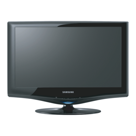
TFT-LCD TV
LA22B350F2
Refer to the service manual in the GSPN (see the rear cover) for the more information.
LCD-TV
Chassis
: N66F
Model
: LA22B350F2
LA22B450C8
Manual
1. Precautions
2. Product specifications
3. Disassembly and Reassembly
4. Troubleshooting
5. Exploded View & Part List
6. Wiring Diagram
Contents
Advertisement
Table of Contents


Need help?
Do you have a question about the LA22B350F2 and is the answer not in the manual?
Questions and answers