Nokia C6-01 Service Manual
Hide thumbs
Also See for C6-01:
- User manual (137 pages) ,
- Manual del usuario (129 pages) ,
- User manual (26 pages)
Table of Contents
Advertisement
Quick Links
See also:
User Manual
1
SERVICE MANUAL
Level 1&2
RM-718 / RM-601
Transceiver characteristics
Band:
GSM 850/900/1800/1900
WCDMA 850/900/1700/1900/2100
GSM 850/900/1800/1900
WCDMA 900/1700/1900/2100
Display:
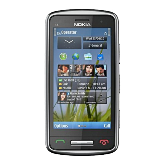
3.2" nHD (640x360 pixels) AMOLED, 16M colors
Camera:
8 Mpix full focus camera, dual LED flash, 2x Digital
zoom. 2
Operating System:
Symbian^3
Connections:
• WCDMA DL 384k HSDPA 10M; UL 384k HSUPA 2M
• GSM CS data 9.6/14.4/HSCSD MSC6
• GSM GPRS data class 32, GSM EGPRS data class 32,
DTM 11
• WLAN IEEE802.11 b/g/n
• USB 2.0 high-speed through micro USB connector.
USB OTG
• Bluetooth wireless technology 3.0 & 2.1 + EDR
Transceiver with BL-5CT battery pack
Talk time
GSM:
Up to 11 hours
WCDMA:
Up to 4 hours
Note:
Talk times are dependent on network parameters
and phone settings
Confidential | Copyright © 2010 Nokia | All rights reserved
Service Manual Level 1&2
VGA camera.
nd
Standby
GSM:
Up to 400 hours
WCDMA:
Up to 450 hours
Nokia C6-01
RM-718 / RM-601
Version 1.0
Advertisement
Table of Contents

Related Manuals for Nokia C6-01


Summary of Contents for Nokia C6-01
- Page 1 Up to 11 hours Up to 400 hours WCDMA: WCDMA: Up to 4 hours Up to 450 hours Note: Talk times are dependent on network parameters and phone settings Confidential | Copyright © 2010 Nokia | All rights reserved Version 1.0...
-
Page 2: Table Of Contents
BATTERY INFORMATION ............................8 EXPLODED VIEW ............................... 9 SERVICE DEVICES ..............................10 SOFTWARE UPDATE ............................... 11 DISASSEMBLY INSTRUCTIONS ..........................12 ASSEMBLY HINTS ..............................20 SOLDER COMPONENTS ............................22 Confidential | Copyright © 2010 Nokia | All rights reserved Version 1.0... - Page 3 2.09.2010 First approved version The purpose of this document is to help NOKIA service levels 1 and 2 workshop technicians to carry out service to NOKIA products. This Service Manual is to be used only by authorized NOKIA service suppliers, and the content of it is confidential. Please note that NOKIA provides also other guidance documents (e.g.
-
Page 4: Copyright
Nokia operates a policy of continuous development. Nokia reserves the right to make changes and improvements to any of the products described in this document without prior notice. Under no circumstances shall Nokia be responsible for any loss of data or income or any special, incidental, consequential or indirect damages howsoever caused. -
Page 5: Warnings And Cautions
3. Use only approved components as specified in the parts list. 4. Ensure all components, modules screws and insulators are correctly re–fitted after servicing and alignment. 5. Ensure all cables and wires are repositioned correctly Confidential | Copyright © 2010 Nokia | All rights reserved Version 1.0... -
Page 6: Esd Protection
RM-718 / RM-601 Service Manual Level 1&2 3. ESD PROTECTION Nokia requires that service points have sufficient ESD protection (against static electricity) when servicing the phone. Any product of which the covers are removed must be handled with ESD protection. The SIM card can be replaced without ESD protection if the product is otherwise ready for use. -
Page 7: Care And Maintenance
All of the above suggestions apply equally to the product, battery, charger or any accessory. Confidential | Copyright © 2010 Nokia | All rights reserved Version 1.0... -
Page 8: Battery Information
Batteries’ performance is particularly limited in temperatures well below freezing. Do not dispose batteries in a fire! Dispose of batteries according to local regulations (e.g. recycling). Do not dispose as household waste. Confidential | Copyright © 2010 Nokia | All rights reserved Version 1.0... -
Page 9: Exploded View
I0014 SCREW TORX+ 6 I0021 ANTENNA I0023 BATTERY COVER ANTENNA DECORATIVE I0025 I0024 Only available Not reuseable Repair/swap Ver. 1.0 as assembly after removal only in level 3 Confidential | Copyright © 2010 Nokia | All rights reserved Version 1.0... -
Page 10: Service Devices
Service Bulletin (SB-011) on Nokia Online. Supplier or manufacturer contacts for tool re-order can be SS-186 Camera Removal tool BL-5CT Battery found in “Recommended service equipment” document on Nokia Online. Confidential | Copyright © 2010 Nokia | All rights reserved Version 1.0... -
Page 11: Software Update
To use the FLS-5 Flash Dongle, follow the user guide inside the sales package. Please check always for the latest version of flash software, which is available on Nokia Online. Confidential | Copyright © 2010 Nokia | All rights reserved... -
Page 12: Disassembly Instructions
6) Lift up the bottom end of the ANTENNA from the shown places. DECORATIVE and then pull it to the direction shown. The ANTENNA DECORATIVE can now be removed. Confidential | Copyright © 2010 Nokia | All rights reserved Version 1.0... - Page 13 11) Open also the two clips on the other side with 12) Use the SS-93 to release the clip holding the B- the SS-93. COVER and the ENGINE BOARD together. Confidential | Copyright © 2010 Nokia | All rights reserved Version 1.0...
- Page 14 17) Open the clip with the SS-93 holding the ENGINE 18) The ENGINE BOARD can now be separated. BOARD and the DISPLAY together. Confidential | Copyright © 2010 Nokia | All rights reserved Version 1.0...
- Page 15 24) To remove the CAMERA MODULE, press down the camera removal tool SS-186 until the camera retaining clips are released. Lift up the SS-186 and remove the CAMERA MODULE. Confidential | Copyright © 2010 Nokia | All rights reserved Version 1.0...
- Page 16 27) Lift up the BUTTON HOLDER. Be careful not to 28) Remove the BUTTON HOLDER. damage the flex. 29) Use the SS-93 to release the clips holding the 30) Remove the KEYMAT. KEYMAT. Confidential | Copyright © 2010 Nokia | All rights reserved Version 1.0...
- Page 17 Discard it. Remove also the EARPIECE adhesive remains. 35) Use the SS-93 to release the PROXY BOOT and 36) Use the SS-93 to lever up the IHF SPEAKER. remove it. Confidential | Copyright © 2010 Nokia | All rights reserved Version 1.0...
- Page 18 39) Use the dental tool to lever up the FLASH PWB. 40) Remove the FLASH PWB with the tweezers. 41) Use the dental tool to lever up the DC JACK. 42) Remove the DC JACK with the tweezers. Confidential | Copyright © 2010 Nokia | All rights reserved Version 1.0...
- Page 19 43) Use the dental tool to lever up the AV JACK. 44) Remove the AV JACK with the tweezers. 45) Nokia C6-01 disassembly is now complete. -END OF DISASSEMBLY- Confidential | Copyright © 2010 Nokia | All rights reserved Version 1.0...
-
Page 20: Assembly Hints
A-COVER connector with the SS-93. Be careful not 93. Be careful not to damage the flex, the connector to damage the flex, the connector or any nearby or any nearby components! components! Confidential | Copyright © 2010 Nokia | All rights reserved Version 1.0... - Page 21 19 Ncm in the order shown. 9) Place the ANTENNA directly on top of the B-COVER. Press the ANTENNA carefully so that the two shown guiding pins are attached. Confidential | Copyright © 2010 Nokia | All rights reserved Version 1.0...
-
Page 22: Solder Components
Nokia C6-01 RM-718 / RM-601 Service Manual Level 1&2 11. SOLDER COMPONENTS Confidential | Copyright © 2010 Nokia | All rights reserved Version 1.0...
Need help?
Do you have a question about the C6-01 and is the answer not in the manual?
Questions and answers