Advertisement
Advertisement
Table of Contents

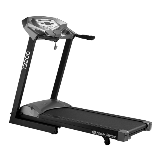
Summary of Contents for Health Master HM-T3200
-
Page 2: Table Of Contents
TABLE OF CONTENTS * SAFETY ----------------- p1~p2 * WARM-UP & COOL DOWN ----------------- * UNPACKING & ASSEMBLY ----------------- * ASSEMBLY DRAWING ----------------- * COMPUTER OPERATIONS ----------------- p6~p7 Control panel function, control panel operation * BELT ADJUSTMENT ----------------- * CARE & MAINTENANCE ----------------- * LUBRICATION MAINTENANCE -----------------... -
Page 3: Safety
SAFETY IMPORTANT: Read all instructions and warnings before using the treadmill IMPORTANT VOLTAGE INFORMATION ! Before plugging the power cord into an electrical outlet, verify that the voltage requirements for your area match the voltage of the treadmill that you have received,. The power requirements for this treadmill include a grounded, dedicated circuit, rated for one of the following: 115VAC +- 5%, 60Hz and 20amps;... - Page 4 SAFETY You do not want to workout at your TARGET HEART RATE ZONE maximum heart rate. The recommended Heart Rate Zone is a percentage of your maximum heart rate. Between 60% and 75% of your maximum heart rate. Lower limit of Target Heart Rate Zone =maximum heart rate X 0.6 Upper limit of Target Heart Rate Zone =Maximum heart rate X0.75...
-
Page 5: Warm-Up & Cool Down
WARM-UP & COOL DOWN WARM- UP& COOL-DOWN A successful exercise program consists of a warm up, aerobic exercise and a cool down. Warming up is an important part of your workout, and should begin every session. It prepares your body for more strenuous exercise by heating up and stretching out your muscles. -
Page 6: Unpacking & Assembly
UNPACKING & ASSEMBLY WARNING!: Use extreme caution when assembling the treadmill. Failure to do so could result in injury NOTE: Each step number in the assembly instructions tells you what you will be doing. Read and understand all instructions thoroughly before assembling the treadmill. 1. -
Page 7: Computer Operations
COMPUTER OPERATIONS CONTROL PANEL FUNCTION FAST/SLOW: CALORIES: indicates TIME: indicates time you workout, Used to adjust speed in 0.1 estimated calories burned can be set to countdown kph increments DISTANCE: indicates km To set programs(P1~P10), PULSE: estimated heart rate travelled in 0.1 increment ,Set time to countdown STOP: Stop the treadmill UP/DOWN:Adjust incline... - Page 8 ASSEMBLY DRAWING STEP 1- Attach the console STEP 2- Attach the console to the masts to the base console masts frame Wire A). connect the upper console wire to lower console wire, connect the grounded wires, assemble the console set to the console mast, Attach with two M8X15 bolts each side using Allen wrench.
-
Page 9: Belt Adjustment
BELT ADJUSTMENT BELT ADJUSTMENT You may need to adjust the running belt during the first few weeks of use. All running belts are properly set at the factory. It may stretch or be off-center after use. Stretching is normal during the break-in period. - Page 10 COMPUTER OPERATIONS PROGRAMS(P2~P15): 1). Power on, put SAFETY KEY on 2). Press "FAST/SLOW" to select programs 3). Press "MODE" to enter count down setting 4). Press "FAST/SLOW" to set exercise time 5). Press " START" to start exercise 6). Adjust speed using " FAST/SLOW" , adjust incline using " UP/DOWN" 7).
-
Page 11: Care & Maintenance
CARE & MAINTENANCE WARNING!:To prevent electrical shock, be certain the treadmill is turned off and unplugged before cleaning or routine maintenance. RUNNING BELT AND RUNNING DECK LUBRICATION For maximum treadmill life, this treadmill needs a routine lubrication as part of a general maintenance for the machine. -
Page 12: Lubrication Maintenance
LUBRICATION MAINTENANCE It is important to take good care of your treadmill deck (the walking surface underneath the belt). A good silicone lubrication will also improve the performance of your treadmill. NOTE: Use the silicone that is supplied with the treadmill. Additional silicone lubricant can be purchased from your retail store. -
Page 13: Trouble Shooting
TROUBLE SHOOTING TROUBLE SHOOTING GUIDE SYMPTO M SOLUTION CAUSE Check the on-off switch a. No power to tread mill Cons ol e di sp lay LCD 's b. Cons ol e wire co nne ct or not Turn off, then turn on power. do not illum inat e co nne ct ed or inc om pl et el y Push START,... -
Page 14: Parts List
PARTS LIST DESCRIPTION ITEM ITEM DESCRIPTION Fixing bracket, safety key ST01-H12 Main frame ST08-AB1 Membrane key ST06-H20 ST01-B19 Fixing bracket, motor ST06-J01 Motor ST06-B21 Rubber cushion ST04-J02 Incline motor ST08-B22 Running belt ST08-B23 ST11-J03 Side rein Controller ST01-J08 ST63-B24 Motor sensor wire Upper motor cover ST08-J09 ST03-B25... -
Page 15: Hardware Kit
PARTS LIST-BOLTS ITEM DESCRIPTION ITEM DESCRIPTION Bolt M10x45 Bolt M8X15mm Incline motor Pad, base frame Nylon nut M10 Bolt M8x50mm Incline motor Foot pad Lift arm Bolt M3x6mm BOLT M8X140mm Monitor Sensor wire, monitor Motor PC board, EZ-button Nylon nut M8 Motor Bolt M8x2 5 mm Folding arm, incline... -
Page 16: Exploded Drawing
EXPLODED DRAWING...
Need help?
Do you have a question about the HM-T3200 and is the answer not in the manual?
Questions and answers