Table of Contents
Advertisement
Quick Links
Advertisement
Table of Contents

Summary of Contents for Jline Quattro
- Page 1 4-CHANNEL FM RADIO SYSTEM INSTRUCTION MANUAL MANUFACTURED BY JR REMOTE COMTROL...
-
Page 3: Table Of Contents
4.2 Receiver Layout ......4 11.1 Quattro Trainer System ....12 4.3 Receiver Specifications . -
Page 4: System Specifications
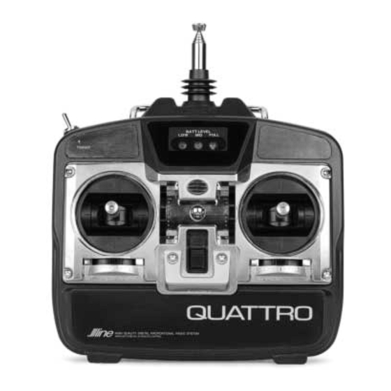
Charger NEC-221 12" Aileron Extension Airborne Battery 4.8V 600mAh NiCad Instruction Manual 3. QUATTRO TRANSMITTER TRANSMITTER FEATURES • Computer-designed, ergonomically styled case • Easy-to-read transmitter LED battery • Servo reversing on all 4 channels (page 12) voltage indicator • Adjustable control stick length (page 5) •... -
Page 5: Transmitter Specifications
There is an eye hook on the front of the transmitter so that the transmitter will be perfectly balanced for attaching an optional neck strap (JRPA023). The when a neck strap is used. eye hook is precisely positioned (see Section 3.2) QUATTRO MANUAL... -
Page 6: Ner-600 Receiver
RECEIVER SPECIFICATIONS Model Number NER-600 Selectivity 8KHz/50db Type 6-Channel FM Weight 1 oz. ABC&W Size (W x L x H) 1.43" x 2.06" x .55" Frequency 72MHz Receiver Antenna 39" for all Aircraft Sensitivity 5ms Minimum Frequencies (Microseconds) QUATTRO MANUAL... -
Page 7: Servo
0.73" x 1.52" x 1.32" (oz/in) (WxLxH) Speed .25 sec/60° Motor 3-Pole Ferrite (sec./60°) Weight 1.47 (oz.) 6. AIRBORNE (RECEIVER) BATTERY PACK Model Number 4N600 Size 2.24" x .59" x 2.05" (WxLxH) Voltage 1.2V x 4 NiCad (4.8V 600mAh) Weight (oz.) QUATTRO MANUAL... -
Page 8: Charger Specifications
100-120V 50mAh Receiver Charging Time 15 Hours 8. CHARGING YOUR QUATTRO RADIO SYSTEM PRIOR TO INSTALLATION Your Quattro Radio System is shipped from the Under normal conditions, subsequent recharging of factory with both the transmitter and receiver your Quattro System will require only an overnight NiCad batteries in a discharged state. -
Page 9: Pre-Installation System Preparation
9. PRE-INSTALLATION SYSTEM PREPARATION FLIGHT PACK CONNECTIONS Connect all flight pack components of your Quattro System as outlined in the diagram below: Receiver Battery 4N600 Not Used With 4-Channel System Not Used With 4-Channel System Connect to Charger On/Off Switch Harness... -
Page 10: 577 Servo Preparation
Servo Eyelet Figure 2 Servo Lead w/Connector SYSTEM CHECK Slide the power ON/OFF switch on your Quattro By moving each of the two transmitter sticks in a Transmitter to the “ON” position. fore-aft, left-right motion, the corresponding throttle, rudder, elevator, and aileron (optional) Next, slide the ON/OFF switch on your flight pack servo arm/wheel will rotate. -
Page 11: Flight Pack Installation
The flange of the brass eyelets should face down (toward the wood). See Section 9.3. Servo Horn 90° with Servo at Control Rod Neutral/Center Position QUATTRO MANUAL... -
Page 12: Servo Reversing
Up Elevator Up Elevator Aileron Throttle Elevator Rudder (Mode II Transmitter Shown) Servo Reversing Switches (Located behind Transmitter Battery Pack) High (Full) Rudder Aileron Down Aileron Up Carburetor Elevator Low (Idle) 1/16" Up Elevator Throttle Right Aileron Right Rudder QUATTRO MANUAL... -
Page 13: Adjusting Control Surface Travel
Quite simply, by moving the control rod in on the original servo horn screw. servo arm/wheel, control surface travel will be QUATTRO MANUAL... -
Page 14: Pre-Flight Information
PPM selectable (FM) J-line or transmitter can be used as either a master (trainer) JR radios that have built-in trainer systems. An or as a slave (trainee). The Quattro is compatible optional trainer cord is needed (JRPA130). Trainer Switch... -
Page 15: General Notes
6. Check to be sure that all servo pigtails and properly secured. switch harness plugs are secure in the receiver. 3. Ensure that all surfaces are moving in the Also, make sure that the switch harness moves proper manner. completely in both directions. QUATTRO MANUAL... -
Page 16: Warranty And Service Information
Mail your system to: during shipping. Horizon Service Center 4105 Fieldstone Road 4. Include detailed information explaining your Champaign, Illinois 61822 operation of the equipment and problem(s) (217) 355-9511 encountered. Provide an itemized list of equipment enclosed and identify any particular QUATTRO MANUAL... -
Page 17: Frequency Chart
15. FREQUENCY CHART 72MHz requires no special license to operate. * It is important that you attach the enclosed frequency ID plates/flag to your Quattro transmitter antenna. 72MHz 72MHz CH.NO. FREQUENCY CH.NO. FREQUENCY 72.090 72.550 72.110 72.570 72.130 72.590 72.150 72.610... - Page 18 NOTES QUATTRO MANUAL...
- Page 20 MANUFACTURED BY JR REMOTE COMTROL DISTRIBUTED EXCLUSIVELY BY HORIZON HOBBY, INC. CHAMPAIGN, IL 61822 www.horizonhobby.com...
Need help?
Do you have a question about the Quattro and is the answer not in the manual?
Questions and answers