
Related Manuals for Mercury M-600 Series

Summary of Contents for Mercury M-600 Series
- Page 1 ...
- Page 3 Thank you for purchasing our Mercury Series. This terminal offers highly enhanced features, with easy connection to various optional devices for optimum performance. This user manual describes how to setup and connect your terminal. © Copyright 2011 All rights reserved. This product and related documentation are protected by copyright and are distributed under licenses restricting their use, copying, and distribution. No part of this documentation may be reproduced in any form by any means without prior written authorization of the manufacturer and its licensors, if any. • Read the safety notices and the User Manual carefully before turning the product ...
- Page 4 If there is any of the following situation arise, notify a qualified service technician immediately: The power cord or plug is damaged. Liquid has been spilt on to the equipment. The equipment has been dropped and damaged. The equipment does not function normally. • Do not block any ventilation openings to prevent the equipment from overheat. • Do not leave the equipment in a non air‐conditioned environment where the storage temperature may go above 70°C (158°F), as this can cause damage to the equipment. e • Gently wipe screen with a clean soft hair lens brush, or a lint‐free cloth. • Do not apply pressure to the screen while cleaning • Do not spray any liquid directly onto the screen or the casing of the Mercury Series Terminal • Chemical cleaners have been reported to cause damage on the screen of the Mercury Terminal. • The technical descriptions and specifications of the equipment are subject to change without notice. • For safety reasons, wear gloves when assembling the product. • Risk of explosion if battery is replaced by an incorrect type. • Dispose of used batteries according to the instructions. •...
- Page 5 Preface This device complies with FCC Rules Part 15. Operation is subject to the following two conditions: • This device may not cause harmful interference. • This device must accept any interference received including interference that may cause undesirable operation. This equipment has been tested and found to comply within the limit of a Class A digital device, pursuant to Part 15 of the FCC Rules. These limits are designed to provide reasonable protection against harmful interference in a residential installation. This equipment generates, uses and can radiate radio frequency energy and, if not installed and used in accordance with the manufacturer’s instructions, may cause harmful interference to radio communications. However, there is no guarantee that interference will not occur in a particular installation. If this equipment does cause harmful interference to radio or television reception, which can be determined by switching the equipment on and off, the user is encouraged to try to correct the interference by one or more of the following measures: • Reorient or relocate the interference receiving antenna. • Increase the distance of separation between the equipment and interference receiver. • Connect the equipment to a power outlet on a circuit different from that to which the interference receiver is connected. • Consult the dealer or an experienced radio/TV technician for help. The use of shielded cables for connection of the monitor to the graphics card is required to assure compliance with FCC regulations. Changes or modifications to this unit not expressly approved by the party responsible for compliance could void the user’s authority to operate this equipment. 连接屏幕与显示卡所使用的防磁缆线必须确实遵守 FCC 规范。未获厂商明确同意而擅 自变更或修改本装置,可能导致使用者的使用权限失效,而无法继续操作本设备。 警告使用者:这是甲類的信息产品,在居住的环境中使用时,可能成射频干扰,在这 种情况使用者会被要求采取某些适当的对策。 連接螢幕與顯示卡所使用的防磁纜線必須確實遵守 FCC 規範。未獲廠商明確同意而擅 自變更或修改本裝置,可能導致使用者的使用權限失效,而無法繼續操作本設備。...
-
Page 6: Table Of Contents
Welcome......................1 Overview of Mercury 600 ..................1 Front View ......................1 Rear View......................2 Connecting to a POS Terminal............... 3 Unpacking ......................4 Getting Started....................5 Pre‐installation Notice................... 5 Default Settings....................6 Limitations......................6 Connector & Jumper Pin Location............... 7 Jumper Setting and Connector Define ............7 System Upgrade....................10 Installing a Hard Disk Drive ................ 10 Memory Configuration ................. 10 Technical Information.................11 Product Specifications ..................11 Frequently Asked Questions (FAQ) ..............13 Troubleshooting .................... -
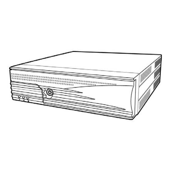
Page 7: Welcome
Congratulations on your purchase of the Mercury 600. This product is specifically designed to offer you enhanced features, speed, and performance to promote your business higher flexibility and a superior customer experience. Pull the front panel outwards to access the front components. Front panel DESCRIPTION 1 Power LED 2 LAN LED 3 HDD LED ... -
Page 8: Rear View
Chapter 1 — Welcome DESCRIPTION 4 Key lock 5 Reset button 6 Power button 7 USB2.0 port 8 2.5” Hard drive disk DESCRIPTION FUNCTION AC power input 1 Connects to an AC power cord. AC outlet by AC switch. 2 VGA output Connects to a POS LCD monitor. 3 COM ports Connect to POS peripherals. 4 USB ports Connect to USB 2.0 devices. 5 MIC in Connects to a microphone. 6 Parallel port Connects to a POS printer. 7 ... -
Page 9: Connecting To A Pos Terminal
Chapter 1 — Welcome The Mercury 600 collaborates with the Pyramid Touch Monitor to expand the capability and the flexibility for your business. Connect one end of the VGA cable to the VGA port on the back of the POS PC. Connect the other end of the VGA cable to the VGA port on the back of the POS LCD Monitor. VGA Cable VGA Port on POS PC ... -
Page 10: Unpacking
Chapter 1 — Welcome Before setting up the Mercury 600, check that the package contains the following items. If any of the items are missing or damaged, contact your vendor immediately. Mercury 600 POS PC AC power cord Accessory package Vertical stand holder (option) Rear cable cover (option) ... -
Page 11: Getting Started
This chapter describes how to install the optional accessories on the Mercury 600 for optimum serviceability. Before you start installing the Mercury 600, please read the following notices carefully The Mercury 600 is an AT type system, it supports ACPI and Wake On LAN feature. The Mercury 600 features one PCI‐E slot. Do not plug in or unplug any interior devices, such as memory module or any function card, when the PSU is powered on. The LAN chipset uses RTL 8111 family network adapter. The Terminal has been built‐in the PXE Boot ROM function within the BIOS to execute Boot ROM already. For installation and compatibility, using the DDR3 RAM Module from the original manufacturer is recommended. The USB device connector is Hot Swap. Do not plug in or unplug any connectors other than USB devices when the power is on. Do not insert or remove any devices or components from the Mercury Series while the power is on. The COM ports support IRQ sharing for DOS application only. A bug may be found when installing Windows 2000 from a USB CDROM. When this occurs, please go to the Microsoft website at http://support.microsoft.com/kb/838921 and find the solution. ... -
Page 12: Default Settings
Chapter 2 — Getting Started Default settings for Mercury POS PC serial ports COM1 COM2 COM3 COM4 3F8 2F8 3E8 2E8 4 3 5 10 Output Voltage COM Port Average Max. Current PIN of COM1 5V / 0.5A, 12V / 0.5A 5V / 0.7A, 12V / 0.6A PIN of COM2 5V / 0.5A, 12V / 0.5A 5V / 0.7A, 12V / 0.6A PIN of COM3 5V / 0.5A, 12V / 0.5A 5V / 0.7A, 12V / 0.6A PIN of COM4 5V / 0.5A, 12V / 0.5A 5V / 0.7A, 12V / 0.6A USB2.0 ports 5V / 0.5A S1 DC12V output (optional) ... -
Page 13: Connector & Jumper Pin Location
Chapter 2 — Getting Started & & This section covers the jumper pin locations for the following: COM 1 / 2 / 3 / 4 D‐Sub 9‐pin selection CMOS clear Cash Drawer voltage setting S‐ATA port power Connector Define J1 Audio line input, line output, and microphone input S1 12V DC power output (optional) S2 Power‐on button S3 Reset button LED1 Power LED LED2 LAN LED LED3 HDD LED ... - Page 14 Chapter 2 — Getting Started CASHDRAW1 Cash Drawer output (optional) OUT4P1/2 DC Power output for S‐ATA HDD/SSD SATA1/SATA2 S‐ATA connector JP7 S‐ATA DOM DC5V connector CN1 24V DC power output (optional) CN2 2*USB connector CN3 2*USB connector + Gigabit LAN CN4 Parallel port connector CN5 COM4 connector CN6+ATX1 ATX power in CN7 Mini PCI‐E socket CN8 2*USB connector CN9 COM1/COM2 connector CN10 COM3 connector + VGA output JP6 S‐ATA PORT POWER 1‐2 DC5V for CN9 Default = 0V 2‐3 0V JP5 CMOS CLEAR JUMPER ...
- Page 15 Chapter 2 — Getting Started JP3 COM2 D‐SUB PIN9 VOLTAGE SELECT 1‐2 = 0V Default = 0V 3‐4 +5V 5‐6 +12V JP2 COM3 D‐SUB PIN9 VOLTAGE SELECT 1‐2 = 0V Default = 0V 3‐4 +5V 5‐6 +12V JP4 COM4 D‐SUB PIN9 VOLTAGE SELECT 1‐2 = 0V Default = 0V 3‐4 +5V 5‐6 +12V J2 CASH DRAWER VOLTAGE SETTING 1‐2 24V Default = 24V 2‐3 12V Note: • Do not plug in or unplug any connector except USB devices when the power is on. ...
-
Page 16: System Upgrade
Your warranty remains in effect only if all internal settings are done by an authorized dealer or technician. This section is intended only for users who wish to perform adjustments by themselves and thereby void the warranty. WARNING: If you purchase a Mercury 600 without a hard disk drive, contact your dealer for system upgrade. You can increase the system memory for the Mercury 600 via onboard DDR3 Socket. The Mercury 600 supports one bank of 256/512/1024/2048MB DIMM Modules. WARNING: Consult your dealer for memory upgrades. ... -
Page 17: Technical Information
ITEM SPECIFICATION Mercury 600, M-POS, M-BOOK Model Name Processor Intel® Pineview‐D D525 1.8GHz (Dual core) Main Memory 204‐pin DDR3 RAM x 1, up to 2GB System Core North Bridge: Intel Pineview D525 Integrated Chip Chipset South Bridge: ICH8M BIOS Award BIOS with enhanced ACPI 1.0 PnP/APM/DMI/ESCD/PCI bus 2.1/ On Now/ DRAM ECC AGP 3D Graphics VIA AGP8X graphics core, share memory from 16MB Port up to 64 MB (16MB Default) Supports 3D/2D graphics accelerator NT 4.0/5.0, Windows 95/98/2000/XP utility APM/ACPI 1.0 DirectX 9.0, VPE, MPEG2 Enhance PCI IDE On board PCI bus master IDE1/2 controller, support Ultra DMA33/66/100/133 Serial ATA Port Two Serial ATA HDD port Parallel Port One LPT port (SPP/EPP/ECP), IRQ and address selectable by BIOS setup Serial Port Total 4 COM port on board (COM1 to COM4), IRQ selectable by BIOS setup (jumper‐less). +5V or +12V output on 9th pin, selectable by jumper ... - Page 18 Appendix — Technical Information ITEM SPECIFICATION USB Total 6 USB port (USB 2.0) Two USB ports (USB2.0) located on the rear panel. Two USB ports (USB2.0) located on the bracket. Two USB ports (USB2.0) located on board. Ethernet Port Realtek RTL‐8111C Ethernet chips on board (10/100/1000M bps) ACPI/NT 4.0/5.0 (NDIS 5) Enable or disable by BIOS setup Audio Port VIA VT 1612A AC97 CODEC on board with Line In/ Line Out/MIC In Expansion Slot One Mini PCI‐E slot ATX 250W internal industrial power adapter AC Power Supply AC 90V to 264V, 60Hz / 50Hz Full Range AC Power Source System Size 280mm (L) x 280mm (W) x 75mm (H) S/W Compatibility DOS/Windows XP/Windows 7/WEPOS/POSReady 2009 Operation Temp. 0°C to 40°C Storage Temp. ‐25°C to 70°C Optional Item DC 24V output DC 12V output RJ‐11 Cash Drawer port (12V/24V) Vertical stand holder Rear Cable Cover Note: Specifications are subject to change without notice. ...
-
Page 19: Frequently Asked Questions (Faq)
Appendix — Technical Information Question 1: Why does the system appear unstable after updating BIOS? Answer: Load optimized defaults (or load SETUP Default) after flashing BIOS. If the system remains unstable, clear CMOS to solve the problem. Question 2: How do I clear CMOS? Answer: To clear CMOS, do the following: Turn off power and switch off the power adapter. Remove the jumper from clear CMOS 2‐3 PIN and insert the jumper to clear CMOS 1‐2 PIN. Remove the jumper from clear CMOS 1‐2 PIN and re‐insert the jumper to clear CMOS 2‐3 PIN. Switch on the power again. Press Delete to enter CMOS setting and load optimized defaults. Save changes and reboot the system. Question 3: How to use the Boot Menu? Answer: To use the Boot Menu, do the following: Press F9 to enter the Boot Menu. Select the Boot device from the Boot Menu. ... -
Page 20: Troubleshooting
Remove all the add‐on cards, and cables from motherboard. Isolate the short pin. Has the motherboard shorted out? Failure has been excluded. Plug in the power of Is the CPU or PSU cooling fan is working properly? Has the the cooling fan. power been connected correctly? Failure has been excluded. Insert and push the memory module Is the memory module correctly installed into the DIMM into the DIMM slot slot? vertically. Failure has been excluded. Plug in AC Power cord and turn on the Mercury POS PC. Next Page ... - Page 21 Appendix — Technical Information The problem may be caused by power supply, CPU, Is the LED on? Is the CPU or PSU fan running? memory, CPU, or memory socket. Failure has been excluded. The VGA card, VGA card slot, or the Is there any image on the display? monitor may be defective. Failure has been excluded. Turn off the system and reboot after the keyboard and the mouse are plugged in. The keyboard or the ...
Need help?
Do you have a question about the M-600 Series and is the answer not in the manual?
Questions and answers