
Related Manuals for Clavister Eagle E5


Summary of Contents for Clavister Eagle E5
- Page 1 Clavister Eagle E5 Getting Started Guide Clavister AB Sjögatan 6J SE-89160 Örnsköldsvik SWEDEN Phone: +46-660-299200 www.clavister.com Published 2014-12-12 Copyright © 2014 Clavister AB...
- Page 2 Clavister. Disclaimer The information in this document is subject to change without notice. Clavister makes no representations or warranties with respect to the contents hereof and specifically disclaims any implied warranties of merchantability or fitness for a particular purpose. Clavister reserves the right to revise this publication and to make changes from time to time in the content hereof without any obligation to notify any person or parties of such revision or changes.
-
Page 3: Table Of Contents
Table of Contents Preface ........................ 5 1. Product Overview ....................7 1.1. Unpacking the Product ................7 1.2. Interfaces and Ports ................. 9 2. Installation ...................... 12 2.1. Installation Guidelines ................12 2.2. Rack Mounting ..................14 2.3. Local Console Port Connection ..............16 2.4. -
Page 4: List Of Figures
List of Figures 1.1. An Unpacked Clavister E5 Appliance ..............7 1.2. Clavister E5 Connection Ports ................9 1.3. The E5 Ethernet Interface Ports ................9 2.1. The E5 Local Console Port ................16 2.2. E5 Power Inlet Socket ..................18... -
Page 5: Preface
The target audience for this guide is the administrator who has taken delivery of a packaged Clavister E5 appliance and is setting it up for the first time. The guide takes the user from unpacking and installation of the device through to power-up, including network connections and initial cOS Core configuration. - Page 6 Where a "See section" link is provided in the main text, this can be clicked on to take the reader directly to that reference. For example, see Section 3.6, “Setup Troubleshooting ”. Web links Web links included in the document are clickable. For example, http://www.clavister.com. Trademarks Certain names in this publication are the trademarks of their respective owners.
-
Page 7: Product Overview
• Interfaces and Ports, page 9 1.1. Unpacking the Product Figure 1.1. An Unpacked Clavister E5 Appliance This section details the unpacking of the E5 appliance. Open the packaging box used for shipping and carefully unpack the contents. The delivered product packaging should contain the following: •... - Page 8 Chapter 1: Product Overview Note: If any items are missing If any items are missing from your package, please contact your reseller or distributor. All relevant documentation can be downloaded in PDF format from the Clavister website. Downloadable E5 Documentation All documentation and other resources for the E5, including this guide, can be downloaded from the E5 product page which can be found at http://www.clavister.com/start.
-
Page 9: Interfaces And Ports
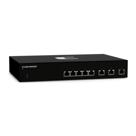
Chapter 1: Product Overview 1.2. Interfaces and Ports This section is an overview of the E5 product's external design. Figure 1.2. Clavister E5 Connection Ports The E5 features the following connection ports on the front panel: • On the left there is a set of RJ45 Gigabit Ethernet interfaces which are numbered 1 to 5. All 5 interfaces are connected together by a common switch fabric and share the single logical cOS Core interface name GESW. - Page 10 Chapter 1: Product Overview • The top-left flashes green to indicate data traffic. • The top-right light is green if the link is 10 or 100 Mb. • The top-right light is amber if the link is 1 Gb. Note: The GESW interface cannot be used with link aggregation If the cOS Core link aggregation feature is used, the logical GESW interface cannot be part of a LinkAggregation object.
- Page 11 Chapter 1: Product Overview...
-
Page 12: Installation
• Connecting Power, page 18 • Resetting to Factory Defaults, page 19 2.1. Installation Guidelines Guidelines Follow these guidelines when installing your Clavister E5 appliance: • Safety Take notice of the safety guidelines laid out in Chapter 5, Safety Precautions. These are specified in multiple languages. - Page 13 Chapter 2: Installation Specifications. • Surge Protection A third party surge protection device should be considered and is strongly recommended as a means to prevent electrical surges reaching the appliance. This is mentioned again in Section 2.4, “Connecting Power”. • Temperature Do not install the appliance in an environment where the ambient temperature during operation might fall outside the specified operating range.
-
Page 14: Rack Mounting
Chapter 2: Installation 2.2. Rack Mounting A Rack Mount Kit is supplied with the E5 for mounting the product in a 19-inch rack. Included with the kit is the following: • 2 x side brackets. • 8 x bracket screws, 4 for securing one bracket to the either side of the E5. The kit is attached to the sides of the E5 unit prior to mounting in the rack. - Page 15 Chapter 2: Installation Repeat this for each side of the E5, so the brackets are mounted as shown below. The E5 is now ready to be rack mounted.
-
Page 16: Local Console Port Connection
Chapter 2: Installation 2.3. Local Console Port Connection The local console port is the physical RJ45 RS-232 port on the far right-hand side front panel of the E5. Figure 2.1. The E5 Local Console Port This local console port allows direct management connection to the appliance, either from a separate computer running console emulation software or from a console terminal. - Page 17 Chapter 2: Installation No parity. iii. 8 bits. 1 stop bit. No flow control. • An RS-232 cable with appropriate terminating connectors. Connection Steps To connect a terminal to the local console port, perform the following steps: Check that the console connection settings are configured as described above. Connect one of the connectors on the cable directly to the local console port on the E5.
-
Page 18: Connecting Power
Chapter 2: Installation 2.4. Connecting Power This section describes connecting power. The E5 has a single internal 12V/2.5A AC to DC power adaptor. As soon as power is applied, the E5 will boot-up and cOS Core will start. Important Please review the electrical safety information in Chapter 5, Safety Precautions. Connecting AC Power To connect power, follow these steps: Plug the end of the power cord into the power inlet on the E5. -
Page 19: Resetting To Factory Defaults
If a console was connected in step 1, the console output will now indicate that the hardware has been reset to its factory defaults. Release the button and the Clavister Security Gateway can now be configured through the console as though it was brand new. - Page 20 Chapter 2: Installation...
-
Page 21: Cos Core Configuration
Clavister's cOS Core network security operating system is preloaded on the E5 and will automatically boot up after power is applied. After boot-up is complete, an external management computer workstation can be used to configure cOS Core. - Page 22 Chapter 3: cOS Core Configuration • Through a web browser. A standard web browser running on a standalone computer (also referred to as the management workstation) can be used to access the cOS Core Web Interface. This provides an intuitive graphical interface for cOS Core management. When this interface is accessed for the first time, a setup wizard runs automatically to guide a new user through key setup steps.
- Page 23 Chapter 3: cOS Core Configuration For connection to the public Internet, another E5 Ethernet interface should be connected to an ISP and this is referred to in the setup wizard as the WAN interface. In this guide, it is assumed that the physical G2 interface of the E5 is used for Internet connection, although any other unused interface could be used instead.
-
Page 24: Web Interface And Wizard Setup
Chapter 3: cOS Core Configuration 3.2. Web Interface and Wizard Setup This chapter describes the setup when accessing cOS Core for the first time through a web browser. The user interface accessed in this way is called the Web Interface. It assumes that a physical network connection has been set up from a management computer to the default management Ethernet interface as described in Section 3.1, “Management Workstation Connection”. - Page 25 Chapter 3: cOS Core Configuration It is possible to configure cOS Core to use a CA signed certificate instead of self-signed certificate for the management login and doing this is described in the cOS Core Administration Guide. The Login Dialog cOS Core will next respond like a web server with the initial login dialog page as shown below.
- Page 26 Chapter 3: cOS Core Configuration the Clavister Security Gateway is being used in Transparent Mode between two internal networks, then the configuration setup is best done with individual Web Interface steps or through the CLI instead of through the wizard.
- Page 27 Chapter 3: cOS Core Configuration Wizard step 3: Select the WAN interface Next, you will be asked for the WAN interface that will be used to connect to an ISP for Internet access. Wizard step 4: Select the WAN interface settings This step selects how the WAN connection to the Internet will function.
- Page 28 Chapter 3: cOS Core Configuration These four different connection options are discussed next in the subsections 4A to 4D that follow. • 4A. Static - manual configuration Information supplied by the ISP should be entered in the next wizard screen. All fields need to be entered except for the Secondary DNS server field.
- Page 29 DNS servers are set automatically after connection with PPTP. Wizard step 5: DHCP server settings If the Clavister Security Gateway is to function as a DHCP server, it can be enabled here in the wizard on a particular interface or configured later.
- Page 30 Chapter 3: cOS Core Configuration Wizard step 6: Helper server settings Optional NTP and Syslog servers can be enabled here in the wizard or configured later. Network Time Protocol servers keep the system date and time accurate. Syslog servers can be used to receive and store log messages sent by cOS Core.
- Page 31 Wizard step 8: License Activation This optional step is to install a license which is fetched from the Clavister website. Internet access will have been set up in previous wizard steps for this option to function. The only input required is a customer username and password.
-
Page 32: Manual Web Interface Setup
Core. Ethernet Interfaces The physical connection of external networks to the Clavister Security Gateway is through the various Ethernet interfaces which are provided by the hardware platform. On first-time startup, cOS Core scans for these interfaces and determines which are available and allocates their names. - Page 33 Chapter 3: cOS Core Configuration Important: The time server URL requires the "dns:" prefix When specifying a URL in cOS Core for the time server, it must have the prefix "dns:". Once the values are set correctly, we can press the OK button to save the values while we move on to more steps in cOS Core configuration.
- Page 34 Reconfiguration is a process that the cOS Core administrator may initiate often. Normally, reconfiguration takes a brief amount of time and causes only a slight delay in traffic throughput. Active user connections through the Clavister Security Gateway should rarely be lost. Tip: How frequently to commit configuration changes It is up to the administrator to decide how many changes to make before activating a new configuration.
- Page 35 IPv4 address 10.5.4.1. The ISP's gateway is the first router hop towards the public Internet from the Clavister Security Gateway. Go to Objects > Address Book in the Web Interface. The current contents of the address book will be listed and will contain a number of predefined objects created by cOS Core after it scans the interfaces for the first time.
- Page 36 Chapter 3: cOS Core Configuration Tip: Creating address book folders New folders can be created when needed and provide a convenient way to group together related IP address objects. The folder name can be chosen to indicate the folder's contents. Now click the Add button at the top left of the list and choose the IP4 Address option to add a new address to the folder.
- Page 37 At this point, the connection to the Internet is configured but no traffic can flow to or from the Internet since all traffic needs a minimum of the following two cOS Core configuration objects to exist before it can flow through the Clavister Security Gateway: •...
- Page 38 Chapter 3: cOS Core Configuration The destination network in the IP rule is specified as the predefined IP4 Address object all-nets. This is used since it cannot be known in advance to which IP address web browsing will be directed and all-nets allows browsing to any IP address. IP rules are processed in a top down fashion, with the search ending at first matching rule.
- Page 39 For the Internet connection to work, a route also needs to be defined so that cOS Core knows on which interface the web browsing traffic should leave the Clavister Security Gateway. This route will define the interface where the network all-nets (in other words, any network) will be found. If the default main routing table is opened by going to Network >...
- Page 40 DHCP client. Usually, a DHCP Host Name does not need to be specified but can sometimes be used by an ISP to uniquely identify this Clavister Security Gateway as a particular DHCP client to the ISP's DHCP server.
- Page 41 Chapter 3: cOS Core Configuration For PPPoE connection, we must create a PPPoE tunnel interface associated with the physical Ethernet interface. Assume that the physical interface is G2 and the PPPoE tunnel object created is called wan_pppoe. Go to Network > Interfaces and VPN > PPPoE and select Add > PPPoE Tunnel.
- Page 42 DHCP Server Setup If the Clavister Security Gateway is to act as a DHCP server then this can be set up in the following way: First, create an IP4 Address object which defines the address range to be handed out. Here, it is assumed that this has the name dhcp_range.
- Page 43 Chapter 3: cOS Core Configuration An example IP pool range might be 196.168.1.10 - 192.168.1.20 with a netmask of 255.255.0.0. In addition, it is important to specify the Default gateway for the server. This will be handed out to DHCP clients on the internal networks so that they know where to find the public Internet. The default gateway is always the IPv4 address of the interface on which the DHCP server is configured, in this case, G1_ip Select the Options tab to set this.
- Page 44 As a further example of setting up IP rules, it can be very useful to allow ICMP Ping requests to flow through the Clavister Security Gateway. As discussed earlier, the cOS Core will drop any traffic unless an IP rule explicitly allows it. Let us suppose that we wish to allow the pinging of external hosts with the ICMP protocol by computers on the internal G1_net network.
- Page 45 The IP rule again has the NAT action and this is necessary if the protected local hosts have private IPv4 addresses. The ICMP requests will be sent out from the Clavister Security Gateway with the IP address of the interface connected to the ISP as the source interface. Responding hosts will send back ICMP responses to this single IP and cOS Core will then forward the response to the correct private IPv4 address.
- Page 46 Chapter 3: cOS Core Configuration Logging can now be enabled on this rule with the desired severity. Click the Log Settings tab, and click the Enable logging box. All log messages generated by this rule will be given the selected severity and which will appear in the text of the log messages. It is up to the administrator to choose the severity and depends on how they would like to classify the messages.
- Page 47 Chapter 3: cOS Core Configuration Doing this is described in Section 3.5, “Installing a License”.
-
Page 48: Cli Setup
Chapter 3: cOS Core Configuration 3.4. CLI Setup This chapter describes the setup steps using CLI commands instead of the setup wizard. The CLI is accessible using either one of two methods: • Using an SSH (Secure Shell) client, across a network connection to the IPv4 address 192.168.1.1 on the default management Ethernet interface. - Page 49 Ethernet Interfaces The connection of external networks to the Clavister Security Gateway is via the various Ethernet interfaces which are provided by the hardware platform. On first-time startup, cOS Core scans for these interfaces and determines which are available and allocates their names. The first interface detected in the scan becomes the initial default management interface and this can only be changed after initial startup.
- Page 50 Chapter 3: cOS Core Configuration Note: Private IPv4 addresses are used for example only Each installation's IP addresses will be different from the example IP addresses but they are used here only to illustrate how setup is done. Also, these addresses are private IPv4 addresses and in reality an ISP would use public IPv4 addresses instead.
- Page 51 Chapter 3: cOS Core Configuration EthernetDevice: 0:G2 1:<empty> AutoSwitchRoute: AutoInterfaceNetworkRoute: AutoDefaultGatewayRoute: ReceiveMulticastTraffic: Auto MemberOfRoutingTable: Comments: <empty> Setting the default gateway on the interface has the additional effect that cOS Core automatically creates a route in the default main routing table that has the network all-nets routed on the interface.
- Page 52 Chapter 3: cOS Core Configuration Device:/> set DNS DNSServer1=dns1_address Assuming a second IP object called dns2_address has been defined, the second DNS server is specified with: Device:/> set DNS DNSServer2=dns2_address B. DHCP - automatic configuration Alternatively, all required IP addresses can be automatically retrieved from the ISP's DHCP server by enabling DHCP on the interface connected to the ISP.
- Page 53 Chapter 3: cOS Core Configuration source interface and source network (in this example, the network G1_net and interface G1 to flow to the destination network all-nets and the destination interface which is the PPPoE tunnel that has been defined. D. PPTP setup For PPTP connection, first create the PPTP tunnel interface.
- Page 54 Chapter 3: cOS Core Configuration DHCP Server Setup If the Clavister Security Gateway is to act as a DHCP server then this can be set up in the following way: First define an IPv4 address object which has the address range that can be handed out. Here, we will use the IPv4 range 192.168.1.10 - 192.168.1.20 as an example and this will be available on the...
- Page 55 The IP rule again has the NAT action and this is necessary if the protected local hosts have private IPv4 addresses. The ICMP requests will be sent out from the Clavister Security Gateway with the IP address of the interface connected to the ISP as the source interface. Responding hosts will send back ICMP responses to this single IP and cOS Core will then forward the response to the correct private IP address.
-
Page 56: Installing A License
Clavister website, then press Activate. The license is fetched automatically across the public Internet and installed. This option is also only available once and that is when installing a license in a Clavister hardware product for the first time. Automatically through the CLI In the CLI, enter the command: Device:/>... - Page 57 The customer username and password login are included in the command with the license fetched automatically across the public Internet. The login credentials are the same ones that are used for the Clavister website. It is then necessary to manually enter the reconf or shutdown command to complete installation.
-
Page 58: Setup Troubleshooting
If the Input counters in the hardware section of the output are not increasing then the error is likely to be in the cabling. However, it may simply be that the packets are not getting to the Clavister Security Gateway in the first place. This can be confirmed with a packet sniffer if it is available. - Page 59 Chapter 3: cOS Core Configuration This will display console messages that show all the ARP packets being received on the different interfaces and confirm that the correct cables are connected to the correct interfaces. To look at the ARP activity only a particular interface, follow the command with the interface name: Device:/>...
-
Page 60: Going Further With Cos Core
IP rules identify the targeted traffic using combinations of the source/destination interface/network combined with protocol type. By default, no IP rules are defined so all traffic is dropped. At least one IP rule needs to be defined before traffic can traverse the Clavister Security Gateway. - Page 61 Staying Informed Clavister maintains an RSS feed of announcements that can be subscribed to at https://forums.clavister.com/rss-feeds/announcements/. It is recommended to subscribe to this feed so that you receive notifications when new releases of cOS Core versions are available for download and installation.
- Page 62 Chapter 3: cOS Core Configuration...
-
Page 63: Warranty Service
Start Date (as defined below). The warranty will only apply to failure of the product if Clavister is informed of the failure not later than two (2) years from the Start Date or thirty (30) days after that the failure was or ought to have been noticed by the customer. - Page 64 Sjögatan 6J 891 60 Örnsköldsvik SWEDEN If the product has not yet been registered with the Clavister through its client web, a proof of purchase (such as a copy of the dated purchase invoice) must be provided with the shipped product.
-
Page 65: Safety Precautions
Chapter 5: Safety Precautions Safety Precautions Clavister E5 devices are Safety Class I products and have protective ground terminals. There must be an uninterrupted safety earth ground from the main power source to the product’s input wiring terminals, power cord, or supplied power cord set. Whenever it is likely that the protection has been impaired, disconnect the power cord until the ground has been restored. - Page 66 Chapter 5: Safety Precautions Informations concernant la sécurité Cet appareil est un produit de classe I et possède une borne de mise à la terre. La source d’alimentation principale doit être munie d’une prise de terre de sécurité installée aux bornes du câblage d’entree, sur le cordon d’alimentation ou le cordon de raccordement fourni avec le produit.
- Page 67 Chapter 5: Safety Precautions • se la vostra LAN copre un’area servita da più di un sistema di distribuzione elettrica, accertatevi che i collegamenti a terra di sicurezza siano ben collegati fra loro; • i cavi LAN possono occasionalmente andare soggetti a pericolose tensioni transitorie (ad esempio, provocate da lampi o disturbi nella griglia d’alimentazione della società...
-
Page 68: E5 Specifications
Appendix A: E5 Specifications Below are the key hardware specifications for the Clavister E5 product. Dimensions, Weight and MTBF Height x Width x Depth (mm) 44 x 280 x 180 Hardware Weight 1.6 kg Hardware Form Factor Desktop 19-inch Rack Mountable... -
Page 69: Declarations Of Conformity
Appendix B: Declarations of Conformity... - Page 70 Appendix B: Declarations of Conformity...
-
Page 71: Port Based Vlan Setup
Appendix C: Port Based VLAN Setup VLAN support on the E5 is divided into two types: • On the Ethernet interfaces G1 and G2, VLANs are created by configuring them normally in cOS Core. It is cOS Core that then takes on the task of adding and recognizing VLAN tags in packets. - Page 72 For this example, the screenshot below shows how this would look in the Web Interface. This last dialog is only available in the Web Interface for Clavister hardware platforms that support port based VLANs. Port Based VLAN Issues...
- Page 73 Clavister AB Sjögatan 6J SE-89160 Örnsköldsvik SWEDEN Phone: +46-660-299200 www.clavister.com...
Need help?
Do you have a question about the Eagle E5 and is the answer not in the manual?
Questions and answers