Table of Contents
Advertisement
INSTALLER: LEAVE THIS MANUAL WITH THE APPLIANCE.
CONSUMER: RETAIN THIS MANUAL FOR FUTURE REFERENCE.
This appliance has been tested to ASTM E 1509, ULC/ORD C1482M-90, ULC S627 AND ULC S628.
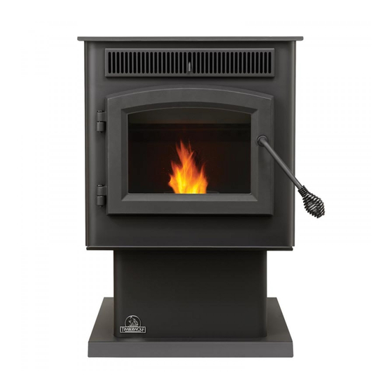
TPS35
PELLET STOVE
TPI35
PELLET INSERT
CERTIFIED FOR CANADA AND UNITED STATES USING ANSI/CSA METHODS.
SAFETY INFORMATION
WARNING
!
PLEASE READ ENTIRE MANUAL
BEFORE YOU INSTALL OR USE THIS
PELLET BURNING APPLIANCE.
If the appliance is not properly installed,
a house fi re may result causing personal
injury or loss of life.
- Authorities having jurisdiction (such as
municipal building department, fi re department,
fi re prevention bureau, etc.) should be consulted
before installation to determine the need to obtain
a permit.
- Contact local building or fi re offi cials about
restrictions and installation inspection
requirements in your area.
- This appliance is hot while in operation. Keep
children, clothing and furniture away. Contact may
cause skin burns.
- Do not start a fi re with chemicals or fl uids such
as gasoline, engine oil, etc...
Phone (705)721-1212 • Fax (705)722-6031 • www.timberwolffi replaces.com • ask@timberwolffi replaces.com
$10.00
OPERATING INSTRUCTIONS
Wolf Steel Ltd., 24 Napoleon Rd., Barrie, ON, L4M 0G8 Canada /
103 Miller Drive, Crittenden, Kentucky, USA, 41030
INSTALLATION AND
1.18B
W415-0865 / B / 05.26.11
1
Advertisement
Table of Contents

Subscribe to Our Youtube Channel
Related Manuals for Timberwolf TPS35


Summary of Contents for Timberwolf TPS35
-
Page 1: Safety Information
Wolf Steel Ltd., 24 Napoleon Rd., Barrie, ON, L4M 0G8 Canada / 103 Miller Drive, Crittenden, Kentucky, USA, 41030 Phone (705)721-1212 • Fax (705)722-6031 • www.timberwolffi replaces.com • ask@timberwolffi replaces.com $10.00 1.18B W415-0865 / B / 05.26.11... -
Page 2: Table Of Contents
TABLE OF CONTENTS INSTALLATION OVERVIEW STOVE INSERT INTRODUCTION DIMENSIONS 2.1.1 STOVE 2.1.2 INSERT (COMPLETE WITH FLASHING) SPECIFICATIONS GENERAL INSTRUCTIONS GENERAL INFORMATION 2.4.1 FUEL 2.4.2 PELLET SPECIFICATIONS 2.4.3 CORN SPECIFICATIONS 2.4.4 SAFETY FEATURES 2.4.5 EPA COMPLIANCE RATING PLATE INFORMATION INSTALLATION PLANNING INSTALLATION OPTIONS APPLIANCE PLACEMENT MINIMUM CLEARANCE TO COMBUSTIBLES... -
Page 3: Installation Overview
10.0 MAINTENANCE 10.1 DAILY (WHENEVER USING THE APPLIANCE) 10.1.1 DISPOSAL OF ASHES 10.1.2 INSPECT THE BURN POT 10.1.3 CARE OF GLASS 10.1.4 CLEANING THE HEAT EXCHANGER TUBES 10.1.5 MAKE SURE PELLETS ARE NOT PILING UP 10.1.6 CLEANING THE BURN POT 10.2 BI-WEEKLY (OR EVERY 10 BAGS OF PELLETS) 10.2.1... -
Page 4: Insert
INSERT Flashing, see “FLASHING INSTALLATION” section. Venting, see “VENTING” and “INSTALLATION” sections. Door, see “FINISHING - INSTALLING THE VIEW- ING DOOR” section. Rating plate, see “RATING PLATE INFORMATION” section. Handle, see “DOOR HANDLE INSTALLATION” section. W415-0865 / B / 05.26.11... -
Page 5: Introduction
2.0 INTRODUCTION WARNING • THIS APPLIANCE IS HOT WHEN OPERATED AND CAN CAUSE SEVERE BURNS IF CONTACTED. • Do not operate appliance before reading and understanding operating instructions. Failure to operate appliance according to operating instructions could cause fi re or injury. Contact the local building or fi re authority and follow their guidelines. Notify your insurance company of this appliance as well. -
Page 6: Dimensions
DIMENSIONS 2.1.1 STOVE " " " " 17" " " CENTRE CENTRE LINE LINE OF " OF AIR INTAKE EXHAUST 2.1.2 INSERT (COMPLETE WITH FLASHING) " " " " CENTRE " LINE OF " CENTRE LINE EXHAUST " CENTRE LINE OF AIR INTAKE OF AIR INTAKE CENTER LINE... -
Page 7: Specifications
SPECIFICATIONS Adjuistable Flashing 11" to 13" 10 1/2" to 12 1/2" Electrical Rating 115 Volts, 3.6 Amps, 60Hz Watts During Ignition Sequence 400 (approximately) Watts During Operation 180 (approximately) Weight Stove 158 lbs / Insert 140 lbs Exhaust Collar 3" Intake Collar 2"... -
Page 8: General Information
Thank you for purchasing a Wolf Steel Ltd. Pellet Appliance. This appliance is designed for use with Pelletized Wood Only. Please read this entire manual before installation and use of this pellet fuel-burning room appliance. Failure to follow these instructions could result in property damage, bodily injury or even death. Keep this manual handy for future reference. -
Page 9: Pellet Specifications
2.4.2 PELLET SPECIFICATIONS WARNING IT IS IMPORTANT TO SELECT AND USE ONLY PELLETS THAT ARE DRY AND FREE OF DIRT OR ANY IMPURITIES SUCH AS HIGH SALT CONTENT. DIRTY FUEL WILL ADVERSELY AFFECT THE OPERA- TION AND PERFORMANCE OF THE APPLIANCE AND WILL VOID THE WARRANTY. THE PELLET FUEL INSTITUTE (P.F.I.) HAS ESTABLISHED STANDARDS FOR WOOD PELLET MANUFACTURERS. -
Page 10: Safety Features
S. ENVIROMENTAL PROTECTION AGENCY C . ENVIROMENTAL PROTECT CLOTHING AND FURNITURE AWAY. CONTACT MAY CAUSE SKIN BURNS. MODÈLE TPS35 APPAREIL DE CHAUFFAGE AUX GRANULES HOMOLOGUÉ TESTÉ SELON LES MODÈLE TPS35 APPAREIL DE CHAU MODÈLE TPS35 APPAREIL DE - INSTALLER ET UTILISER CONFORMÉMENT AUX INSTRUCTIONS DU FABRICANT ET AUX CODES DU BÂTIMENT LOCAUX. -
Page 11: Installation Planning
3.0 INSTALLATION PLANNING WARNING READ ENTIRE MANUAL BEFORE YOU INSTALL OR USE THIS APPLIANCE. FAILURE TO FOLLOW THE INSTRUCTIONS MAY RESULT IN PROPERTY DAMAGE, BODILY INJURY OR EVEN DEATH. USE ONLY WOLF STEEL APPROVED OPTIONAL ACCESSORIES AND REPLACEMENT PARTS WITH THIS APPLIANCE. -
Page 12: Minimum Clearance To Combustibles
MINIMUM CLEARANCE TO COMBUSTIBLES WARNING DO NOT INSTALL INTO ANY AREA HAVING LESS THAN 48" (CEILING TO APPLIANCE BOTTOM, EXCLUDING HEARTH HEIGHT). 3.3.1 STRAIGHT INSTALLATION Interior Vertical Vents Through the Wall Installations complete with outside air 3” 3” 2” 6” 6”... -
Page 13: Floor Protection Requirements Installation
FLOOR PROTECTION REQUIREMENTS INSTALLATION The appliance must be installed on a non-combustible fl oor protector extending the full depth of the appliance and extending a minimum 6" in front and on either side (minimum .018" thick - 26 gauge) of the fuel loading and ash removal openings. -
Page 14: Venting
4.0 VENTING TYPE OF VENT Must be an approved 3" or 4" diameter Type "L" or "PL" vent, vented to the outside or connect the vent to a factory built type "A" chimney using an adaptor; and/or stainless steel chimney liner for masonry appliance in- stallations. -
Page 15: Pellet Vent Termination
PELLET VENT TERMINATION The vent termination must have an approved cap (to prevent water from entering) or a 45° downturn. If the termination is located on a windy side of the house, a shield is recommended to prevent soot from build- ing up on the side of the house. -
Page 16: Stove Venting Installation Examples
STOVE VENTING INSTALLATION EXAMPLES 4.6.1 HORIZONTAL TERMINATION (THROUGH WALL) 3” Minimum 12” Minimum Wall Thimble 6” Minimum 5’ Maximum 11 5/8” Floor 17” Protection Outside Air (Recommended) 4.6.2 VERTICAL RISE HORIZONTAL TERMINATION (THROUGH WALL) Wall Thimble Outside Air (Recommended) 3” 2”... -
Page 17: Vertical Termination
4.6.3 VERTICAL TERMINATION Vertical Cap Storm Collar Roof Flashing Vent must maintain 3” Ceiling Support clearance to combus- tibles. 3” 2” Floor Protection Outside air (Recommended) (Installation showing inlet of out- side air in ventilated crawl space) 4.6.4 CLASS A CHIMNEY RETROFIT Vertical Cap Storm Collar Roof Flashing... -
Page 18: Hearth Mount Installation
4.6.5 HEARTH MOUNT INSTALLATION Vertical Cap Chimney Cap Storm Collar Storm Co Pellet Liner Flue Cover Pellet Clean-out Vent 6” Floor Protection Floor Protect Bring outside air to the stove Outside Air (Recommended) Outside Air (R Recommended) W415-0865 / B / 05.26.11... -
Page 19: Insert Venting Installation Examples
INSERT VENTING INSTALLATION EXAMPLES 4.7.1 TYPICAL EXISTING MASONRY INSTALLATION WARNING DO NOT REMOVE BRICKS OR MORTAR FROM THE FIREPLACE. Prior to installation: Vertical Cap rtical Cap When installing the insert into a masonry fi replace, do not Storm Collar orm Collar remove any bricks or masonry. -
Page 20: Factory Built Fireplace
4.7.2 FACTORY BUILT FIREPLACE Prior to installation: Vertical Do not weaken the structure, or reduce the protection for combustible materials to less then that required by the National Building Code. Bolted or screwed together pieces (smoke shelf / Storm Collar defl... -
Page 21: Framing (Insert Only)
5.0 FRAMING (INSERT ONLY) WARNING RISK OF FIRE! IN ORDER TO AVOID THE POSSIBILITY OF EXPOSED INSULATION OR VAPOUR BARRIER COMING IN CONTACT WITH THE APPLIANCE BODY, IT IS RECOMMENDED THAT THE WALLS OF THE APPLIANCE ENCLOSURE BE “FINISHED” (IE: DRYWALL / SHEETROCK), AS YOU WOULD FINISH ANY OTHER OUTSIDE WALL OF A HOME. -
Page 22: Installation Into A Combustible Enclosure
INSTALLATION INTO A COMBUSTIBLE ENCLOSURE WARNING OUTSIDE AIR IS MANDATORY FOR A COMBUSTIBLE BUILT-IN ENCLOSURE INSTALL. When installing the insert as a "Built-in" appliance, it is important to maintain the clearances to combustibles, see "MINIMUM CLEARANCE TO COMBUSTIBLES" section. A non-combustible hearth must cover the fl ooring underneath, as well as, a minimum of six inches in front and to both sides of the appliance. -
Page 23: Minimum Enclosure Clearances
MINIMUM ENCLOSURE CLEARANCES 6 3/8” MIN. 2” MIN. 40” MIN. 3” all around (Refer to vent manufacturer’s instructions) 27” MIN. 7 1/8” 6” 1 7/8” Non-combustible floor protection MINIMUM CLEARANCE TO COMBUSTIBLES Side wall to appliance 8" Mantel to top of appliance 8"... -
Page 24: Minimum Mantel Clearances
MINIMUM MANTEL CLEARANCES WARNING RISK OF FIRE, MAINTAIN ALL SPECIFIED AIR SPACE CLEARANCES TO COMBUSTIBLES. FAILURE TO COMPLY WITH THESE INSTRUCTIONS MAY CAUSE A FIRE OR CAUSE THE APPLIANCE TO OVERHEAT. ENSURE ALL CLEARANCES (I.E. BACK, SIDE, TOP, VENT, MANTEL, FRONT, ETC.) ARE CLEARLY MAINTAINED. -
Page 25: Finishing
6.0 FINISHING INSTALLING VIEWING DOOR WARNING GLASS MAY BE HOT, DO NOT TOUCH GLASS UNTIL COOLED. THE DOOR LATCHES ARE PART OF A SAFETY SYSTEM AND MUST BE PROPERLY ENGAGED. DO NOT OPERATE THE APPLIANCE WITH LATCHES DISENGAGED. BEFORE DOOR IS REMOVED TURN THE APPLIANCE OFF AND WAIT UNTIL APPLIANCE IS COOL TO THE TOUCH. -
Page 26: Door Handle Installation
DOOR HANDLE INSTALLATION NOTE: DOOR MAY NOT BE AS ILLUSTRATED FRONT VIEW DOOR DOOR HANDLE LATCH LOCK WASHER SPACER SPRING DOOR WASHER HANDLE NOTE: Position of door handle latch. 98.1 DECORATIVE INSET W415-0865 / B / 05.26.11... -
Page 27: Flashing Installation
FLASHING INSTALLATION Secure the left fl ashing to the left side with the three screws provided. Repeat for the right side. Side panels are attached to the fi rebox by the three magnets per side. Lower the top panel, aligning the slots in the top panel with the holes in the side panel. Secure the top panel by to the side panels with the screws and washers provided. -
Page 28: Wiring Diagram
7.0 WIRING DIAGRAM WARNING DO NOT USE THIS APPLIANCE IF ANY PART HAS BEEN UNDER WATER. CALL A QUALIFIED SERVICE TECHNICIAN IMMEDIATELY TO HAVE THE APPLIANCE INSPECTED FOR DAMAGE TO THE ELECTRICAL CIRCUIT. RISK OF ELECTRICAL SHOCK OR EXPLOSION. DO NOT WIRE 110V TO THE VALVE OR TO THE APPLIANCE WALL SWITCH. -
Page 29: Operating Instructions
8.0 OPERATING INSTRUCTIONS PROPER PELLET LOADING Before loading pellets into the hopper fi rst transfer the pellets from it’s original plastic bag to a metal bucket. Keep in mind that the auger stops when the lid is opened. If the lid is opened for several minutes, the fi re may extinguish. -
Page 30: Lighting Instructions
LIGHTING INSTRUCTIONS After fi lling the hopper with pellets, switch the control to manual so that you have full control of the appliance until you have familiarized yourself with its functions. Do not try to operate your appliance with the viewing door or hopper lid open. Safety switches will disable the pellet feed auger. -
Page 31: Control Adjustment
CONTROL ADJUSTMENT FEED TRIM Both the combustion fan speed and the feed rate have been factory set but may need to be adjusted (trimmed) on site. Due to the variables (i.e. vent size, length and pellet quality), the factory settings may not be ideal for every installation. -
Page 32: Normal Operating Sounds
9.0 NORMAL OPERATING SOUNDS CONVECTION BLOWER EXHAUST BLOWER A low hum might be heard due to the high The flow of exhaust gases may efficiency fan, especially on high. create a low-pitched hum. As the pellet feed rate is altered this sound will change. -
Page 33: Maintenance
10.0 MAINTENANCE 10.1 DAILY (WHENEVER USING THE APPLIANCE) WARNING THE FRONT OF THE APPLIANCE BECOMES VERY HOT DURING OPERATION. LET THE APPLIANCE COOL COMPLETELY BEFORE CONDUCTING SERVICE. 10.1.1 DISPOSAL OF ASHES Ashes should be placed in a metal container with a tight fi tting lid. The container should be placed on a non- combustible fl... -
Page 34: Cleaning The Heat Exchanger Tubes
10.1.4 CLEANING THE HEAT EXCHANGER TUBES WARNING THE FRONT EDGE OF THE HOPPER LID BECOMES VERY HOT, DO NOT TOUCH THE AREA BELOW THE HANDLE. THIS ROD BECOMES VERY HOT DURING OPERATION. WAIT UNTIL APPLIANCE HAS COOLED COMPLETELY OR WEAR HEAT RESISTANT GLOVES WHEN CLEANING OR HANDLING THIS APPLIANCE. -
Page 35: Cleaning The Burn Pot
10.1.6 CLEANING THE BURN POT WARNING MAKE CERTAIN THE HEATER HAS FULLY COOLED (APPROXIMATELY 25 MINUTES) BEFORE OPENING THE DOOR AND To clean the burn pot, open the door and knock away any debris on the burn pot. If severely clogged, remove the burn pot to gain better access. If removing the burn pot set aside on a non-combustible surface. -
Page 36: Semi-Annually (Or Every Two Tons Of Pellet)
10.3 SEMI-ANNUALLY (OR EVERY TWO TONS OF PELLET) WARNING THE FIREBOX BECOMES VERY HOT DURING OPERATION. LET THE APPLIANCE COOL COMPLETELY BEFORE CONDUCTING SERVICE. DISCONNECT THE POWER CORD PRIOR TO CONDUCTING SERVICE. THE FOLLOWING SECTION DETAILS EXTENSIVE MAINTENANCE PROCEDURES. WE STRONGLY SUGGEST THESE ITEMS BE CARRIED OUT BY A TRAINED SERVICE TECHNICIAN, POSSIBLY BY A SERVICE AGREEMENT SET UP WITH YOUR DEALER. -
Page 37: Clean The Exhaust Blower
10.3.4 CLEAN THE EXHAUST BLOWER NOTE: Do not attempt this maintenance without a NUTS replacement exhaust blower motor mounting gasket. Remove the six nuts holding the exhaust blower motor in place. Pull the motor out being careful not to damage the wiring, unplug the two wires that are connecting the motor and gently set aside. -
Page 38: Clean The Vent
10.3.6 CLEAN THE VENT WARNING WHENEVER ANY PORTION OF THE PELLET VENT IS DISCONNECTED, THE JOINTS MUST BE RE-SEALED WITH RTV 500°F SILICONE SEALANT. Vent system should be cleaned Make sure the cap is free of using chimney sweep brushes. We debris (especially if it has a recommend this be done by a qualifi... -
Page 39: Replacements
HIGH LIMIT SWITCH 200°F (93°C) W660-0056 VACUUM SWITCH W325-0043 HANDLE, SPRING W195-0004 POWER CORD W435-0019 AUGER MOTOR W062-0025 CONVECTION BLOWER (TPS35) W062-0030 CONVECTION BLOWER (TPI35) W062-0027 COMBUSTION BLOWER W290-0111 COMBUSTION BLOWER MOUNTING GASKET W290-0120 COMBUSTION BLOWER MOTOR MOUNTING GASKET W290-0113... - Page 40 ACCESSORIES PART NO. DESCRIPTION 114KT OUTSIDE AIR KIT - 5 FT (2" DIA.) TPHE HOPPER EXTENSION (INCREASES HOPPER CAPACITY FROM 45 LBS TO 100 LBS PELLETS) STOVE ONLY TI800 FLASHING KIT (INCLUDES FLASHING/SURROUND, SMALL HOPPER DOOR) THERMOSTATIC REMOTE F50-6 BULK THERMOSTATIC REMOTE PAINT, THURMALOX - BLACK ON/OFF REMOTE F40-6...
-
Page 41: Troubleshooting
12.0 TROUBLESHOOTING WARNING TURN OFF THE ELECTRICAL POWER BEFORE SERVICING THE APPLIANCE. APPLIANCE MAY BE HOT, DO NOT SERVICE UNTIL APPLIANCE HAS COOLED. DO NOT USE ABRASIVE CLEANERS. WHEN CHECKING CONNECTIONS, INSTALLING JUMPER WIRES (FOR TEST PURPOSES ONLY) OR REPLACING COMPONENTS, UNPLUG APPLIANCE FROM THE RECEPTACLE TO PREVENT ELECTRI- CAL SHOCK OR DAMAGE TO THE COMPONENT. - Page 42 PROBLEM SOLUTION The ignitor will not light Poor quality or damp pellets take longer to light. the pellets however Push the burn pot back against the ignitor tube making sure the ignitor lines up to everything else in the the hole in the burn pot. appliance operates.
- Page 43 PROBLEM SOLUTION The appliance Due to different installation set ups, length and size of venting and fuel quality, the keeps going out. low feed setting from the factory will not always be correct. It may be necessary to experiment with feed rate vs air control. If the appliance goes out and leaves fresh unburned pellets or cigarette-like ashes in the burn pot, the fi...
-
Page 44: Warranty
After the fi rst year, with respect to the TIMBERWOLF’S Limited Warranty, Wolf Steel may, at its discretion, fully discharge all obligations with respect to this warranty by refunding to the original warranted purchaser the wholesale price of any warranted but defective parts. -
Page 45: Service History
14.0 SERVICE HISTORY 43.1 W415-0865 / B / 05.26.11... - Page 46 15.0 NOTES 44.1 W415-0865 / B / 05.26.11...
- Page 47 44.1 W415-0865 / B / 05.26.11...
- Page 48 44.1 W415-0865 / B / 05.26.11...
Need help?
Do you have a question about the TPS35 and is the answer not in the manual?
Questions and answers