
Summary of Contents for MGP WRM2
- Page 1 OPERATING MANUAL WRM2 Wireless Remote Monitoring System 2 Document # 15-00043 Revision 3 September 2005...
-
Page 2: Revision Log
Mode Summary Modify Figure 4 – Front Panel Changes made to reflect actual operation of rotary switch mode positions and description for WRM2 Base Transceiver Modify Table 3 to include baud rate settings for devices connected to the WRM2 External Transceiver General edits The publication, translation or reproduction, either party or wholly, of this document are not allowed without our written consent. -
Page 3: Revision
OEM product, these fixed antennas require installation preventing end users from replacing them with non-approved antennas. Any antennas not supplied by MGP Instruments must be tested to comply with FCC Section 15.203 for unique antenna connectors and section 15 emissions. -
Page 4: Table Of Contents
Usage ........................27 2.4.6 Battery ........................27 Technical Characteristics ........................28 PAM TRX ..........................28 WRM2 Base Transceiver ....................... 29 WRM2 Repeater........................30 WRM2 EXT..........................31 4.0 Recommended Spare Parts List ........................ 32 PAM-TRX Transceiver ......................32 WRM-2 Base .......................... 32 WRM-2 Repeater and External Transmitter................ -
Page 5: Introduction
Revision 3 September 2005 1.0 Introduction The WRM2 telemetry system incorporates the features of multiple personnel devices into an integrated package. The WRM2 telemetry system components include: Compact Transmitter, Base Transceiver, Repeater and External Transceiver. The WRM2 Compact Transmitter, named “PAM-TRX”, (Personal Alarm Module Transmitter) is a multi- functioning transmitter for the DMC-2000 electronic dosimeter with enhanced alarm notifications and options for various frequencies. -
Page 6: Equipment Description & Operation
15-00043 Revision 3 September 2005 2.0 Equipment Description & Operation PAM-TRX (Personal Alarm Module Transmitter) 2.1.1 Features: • High volume buzzer, 85 dBA at 2200 ± 500 Hz mounted on the top of the enclosure facing the user • Two high intensity multicolor LED’s. One facing the user on top of the enclosure and one on the enclosure front to facilitate monitoring by other workers in the vicinity of the user. -
Page 7: Operation
15-00043 Revision 3 September 2005 Figure 1: PAM TRX Complete Assembly View window for Antenna Speaker/LED Rear Case Dosimeter S/N Cover Pushbutton Clip Transmitter (under board) Infrared Ports (3) ISO Connector Slide Switch Reed (ILS) Test Button Switch access Battery Battery DIP Switch Compartment... - Page 8 15-00043 Revision 3 September 2005 The PAM-TRX is designed to transmit the TTL RS-232 data packet from the dosimeter when the DMC-2000 is configured with transmission ON, 4800 BAUD, Triggered. The unit is compatible with all the DMC family gamma dosimeters data formats (DMC2000S, X and SOR/R). Preparation for use: 2.1.2.1 To open the back case: remove the locking screw and slide off the battery cover.
-
Page 9: Dip Switch Settings
15-00043 Revision 3 September 2005 Test Button Access Reed Switch location (refer to Figure 1) Battery Cover 2.1.3 Slide (DIP) Switch Settings The slide (DIP) switch can be observed (Figure 1) when the back cover is removed for installation or removal of the dosimeter. If changes need to be made to the slide switch, open the case on the rear of the unit. -
Page 10: Operational Test
15-00043 Revision 3 September 2005 The PAM-TRX has been designed to drive an external LED or high impedance Earphone that follows the alarm signal. The stereo alarm connector is compatible with MGPI external alarm devices like the EAM and the PEA-100 in the event that the user desires to use the PAM-TRX as a wireless area-monitoring device or further enhance the volume of the audio signal to over 100 dBA. -
Page 11: Wrm2 Base Transceiver
15-00043 Revision 3 September 2005 2.1.7.5 Perform an operational test. Check the polarity of the batteries if the unit fails the test. 2.2 WRM2 Base Transceiver 2.2.1 Features: • Compact size self-contained transceiver unit. • Compatible with all available frequencies. CE compliant with FHSS 2.4 GHz and 868 MHz radio installed. -
Page 12: Operation
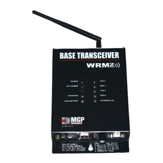
Revision 3 September 2005 Figure 3 below, depicts an image of the single radio WRM-2 Base Transceiver. Figure 3: WRM2 Base Transceiver 2.2.2 Operation The WRM-2 Base Transceiver is a simple device that, after factory configuration, requires no special configuration to operate. The single radio Base unit is pre-configured to operate with same frequency transmitters (normally delivered with the system). - Page 13 15-00043 Revision 3 September 2005 Figure 4 below depicts the configuration of the front panel: Figure 4 – Front Panel Figure 5 below depicts the back panel of the base with one or two RPSMA connectors to connect the antennas. Figure 5 –...
-
Page 14: Radio And Network Adaptor Configuration
NIA (no transmit capability via the NIA). The radio can also be configured in this mode position and requires a specially designed software program. CAUTION: The WRM2 Radios are optimally configured for use with all WRM2 components and should not be modified. Contact MGP Instruments for further information. - Page 15 To program the network adapter: 1. Power ON the WRM2 Base unit. 2. Set the Rotary Mode Selector to Position 3. 3. Connect a straight RS-232 (9-pin Serial Cable) to the DB-9 connector of the Base unit and PC 4.
- Page 16 15-00043 Revision 3 September 2005 Figure 7: Select COM Port 7. Select the “connect using” field to identify the available COM ports and select. - Click OK. 8. The Communication Settings should be set as depicted in Figure 8 below (change as necessary).
- Page 17 15-00043 Revision 3 September 2005 9. Once HyperTerminal has established a connection to the Base unit, press any key on the PC keyboard to enter the configuration mode of the network adapter. The following screen is displayed: Figure 9: Network Configuration 10.
- Page 18 15-00043 Revision 3 September 2005 Select 1 and press ENTER. - Change the IP Address (in accordance with the facility network scheme) and press ENTER. Perform changes, as appropriate, that meet specific network settings (as identified in Figure 10 above) for: - IP Address - Netmask - Gateway...
-
Page 19: Batteries
15-00043 Revision 3 September 2005 If the base has been optionally configured with 2 radios, in this position Radio 1 serial data output is connected to the Radio-2 serial input in order for Radio-2 to transmit any RF data received by Radio-1 at once. -
Page 20: Operational Test
15-00043 Revision 3 September 2005 Eight (8) ‘AAA’ size NiMH batteries can power the WRM Base when external power fails for up to 4 hours. The base circuitry is configured to charge the batteries and provide warning when the battery voltage is too low to properly operate the base. The battery shelf life is expected to be 7 to 10 years. -
Page 21: Wrm-2 Repeater
15-00043 Revision 3 September 2005 WRM-2 Repeater 2.3.1 Features: • Compact and rugged unit used to repeat signals from and to remote units when the PAM-TRX units are outside the normal reception range of the base unit. • Uses the same radio modules as the PAM-TRX and Base Transceiver. •... -
Page 22: Operation
Cell Switch Indicator Connector Figure 15: WRM2 Repeater Front Panel and Battery Compartment 2.3.3 Settings Following factory configuration, no special settings are required to operate the repeater. The radio must be configured to operate in the same frequency and channel as the Base and PAM- TRX. -
Page 23: Operational Test
15-00043 Revision 3 September 2005 2.3.4 Operational Test The repeater can be tested using the same sequence as the base unit described in section 2.2.5. Turn the unit ON using the front panel power switch. Ensure the power LED (green) is illuminated. -
Page 24: Wrm2 Ext - External Transceiver
15-00043 Revision 3 September 2005 WRM2 EXT – External Transceiver 2.4.1 Features • Compact and rugged unit used to transmit signals from and to instruments fitted with RS- 232 output capabilities like the AMP family survey meters, RAM-R200, Ram Ion, ABPM 203M CAM, Telepole, ABPM monitors, and similar. -
Page 25: Operation
15-00043 Revision 3 September 2005 2.4.2 Operation The WRM-2 EXT is a compact unit used to transmit and/or receive serial data in TTL or standard RS-232 from HP instruments to a WRM-2 Base and Repeaters. Because of the open and flexible protocol used by the WRM-2 EXT, any device with RS-232 capability could be connected to the WRM-2 System like body temperature or heart rate sensors, GPS monitors, and chemical or biological detection systems. -
Page 26: Settings
Pin 1 can be configured for VDC output (5V or 7-15 VDC) or input (DMC/AMP connection) or for RXD for two-way communications. • Slide (DIP) Switch configuration for the EXT is depicted in Table 3 below: Table 3: WRM2 EXT Slide Switch & Baud Rate Parameters SW 1 SW 2 SW 3... -
Page 27: Operational Test
15-00043 Revision 3 September 2005 2.4.4 Operational Test The EXT can be tested using the same sequence as the base unit described in section 2.2.5. Turn the unit ON using the front panel power switch. Make sure power LED (green) is lit. Install the correct antenna to ensure matching frequency. -
Page 28: Technical Characteristics
15-00043 Revision 3 September 2005 3.0 Technical Characteristics PAM TRX Transmitter Characteristics • Transmit power output 140 mW (900 MHz), 50 mW (2.4 GHz), 3.5 mW (868 MHz) • Radio sensitivity -110 dBm (900 MHz) and –105 dBm (2.4 GHz). •... -
Page 29: Wrm2 Base Transceiver
15-00043 Revision 3 September 2005 WRM2 Base Transceiver Base Characteristics • Transmit power output 140 mW (900 MHz), 50 mW (2.4 GHz), 3.5 mW (868 MHz) • Receiver sensitivity -110 dBm (900 MHz) and –105 dBm (2.4 GHz). • 868 MHz, 900 MHz or 2.4 GHz spread spectrum hopper (FHSS) •... -
Page 30: Wrm2 Repeater
15-00043 Revision 3 September 2005 WRM2 Repeater Repeater Characteristics • Transmit power output 140 mW (900 MHz), 50 mW (2.4 GHz), 3.5 mW (868 MHz) • Receiver sensitivity -110 dBm (900 MHz) and –105 dBm (2.4 GHz). • 868 MHz, 900 MHz or 2.4 GHz spread spectrum hopper (FHSS) •... -
Page 31: Wrm2 Ext
15-00043 Revision 3 September 2005 WRM2 EXT External Transmitter Characteristics • Transmit power output 140 mW (900 MHz), 50 mW (2.4 GHz), 3.5 mW (868 MHz) • Receiver sensitivity -110 dBm (900 MHz) and –105 dBm (2.4 GHz). • 868 MHz, 900 MHz or 2.4 GHz spread spectrum hopper (FHSS) •... -
Page 32: Recommended Spare Parts List
15-00043 Revision 3 September 2005 Recommended Spare Parts List PAM-TRX Transceiver WR2-9000 (900 MHz), WR2-9100 (2.4 GHz) Quantity Description/Manufacturer/Part Number Comments Main PCB, WR2-9005 Radio Module 900 MHz – WR2-7000 MGPI VID number only. 2.4 GHz – WR2-7002 Commercial version will not work on 868 MHz –... -
Page 33: Wrm-2 Repeater And External Transmitter
15-00043 Revision 3 September 2005 WRM-2 Repeater WR2-9002 (900 MHz), WR2-9102 (2.4 GHz) and External Transmitter WR2-9003 (900 MHz), WR2-9103 (2.4 GHz) Quantity Description/Manufacturer/Part Number Comments Radio Module 900 MHz – WR2-1003 RPSMA Connector 2.4 GHz – WR2-1004 868 MHz – WR2-1005 Antenna 900 MHz –... -
Page 34: Appendix 1: Dosimeter Data Protocol
15-00043 Revision 3 September 2005 APPENDIX 1 Dosimeter Data Protocol This document describes the data exchange protocol used between a DMC series dosimeter in 4800 BAUD and a PAM-TRX sent to a Base or Repeater. Dosimeter Settings The correct dosimeter settings for the dosimeter are as follows: Status word 5 (accessible from Message 11) Bit 0 set to 1... - Page 35 15-00043 Revision 3 September 2005 Table A1-1: Data Format Line Feed Dosimeter Serial Number N5N4N3N2N1N0 Status 1 MSB Dosimeter’s dose and dose rate alarms and status. Status 1 LSB Accumulated Dose D5D4D3D2D1D0.D-1 mrem Not used STATUS 5 (MSB) Configuration Parameters STATUS 5 (LSB) Gamma Dose rate X,YZ * 10...
-
Page 36: Appendix 2: Alternate Network Adapter Programming
1. Install the Moxa Network Enabler Administrator 2. Power up the WRM2 base station 3. Connect the network cable to the RJ 45 connector on the WRM2 and to a network hub 4. Launch the Network Enabler Administrator software 5. Click on ‘Configuration’, then ‘Broadcast Search’ to find the factory default IP address 6. - Page 37 15-00043 Revision 3 September 2005 8. Click on the network tab and check the ‘Modify’ box to edit parameter settings that meet your network settings (Figure A2-3 below): Figure A2-3: Network Parameters 9. Once the network TCP/IP is set, configure the serial port. Select the serial screen and highlight the port.
- Page 38 15-00043 Revision 3 September 2005 Figure A2-4 Serial Configuration 12. Serial Port Configuration Figure A2-5: Serial Port Settings 13. Once the network adapter is configured with the correct IP address (in accordance with facility Information Technology organizations), the network configurations can be accessed using Internet browser running JAVA.
- Page 39 15-00043 Revision 3 September 2005 Figure A2-6: Web Console for Network Enabler Software 14. From this screen go to Operating Settings, Port 1 and set the Max Connection to 4 as shown in Figure A2-7 and select the Local TCP Port to be used in WinWRM2 or Telecast configuration. The default value is 4001.
- Page 40 15-00043 Revision 3 September 2005 Figure A2-7: Operating Settings (Web Console) The publication, translation or reproduction, either party or wholly, of this document are not allowed without our written consent.
Need help?
Do you have a question about the WRM2 and is the answer not in the manual?
Questions and answers