Advertisement
Advertisement
Table of Contents

Summary of Contents for Synel PRX-40/A Proximity SY-11
- Page 1 Stand-Alone Terminals PRX-40/A Proximity SY-11 Magnetic/Barcode Product Manual...
- Page 2 This document has been prepared for reader-controllers PRX-40/A (firmware version 2.08) and SY-11 (firmware version 2.03). Copyright © 1998-2005 Synel Industries Ltd. All rights reserved. Reproduction or use, without express permission of editorial or pictorial content, in any manner is prohibited.
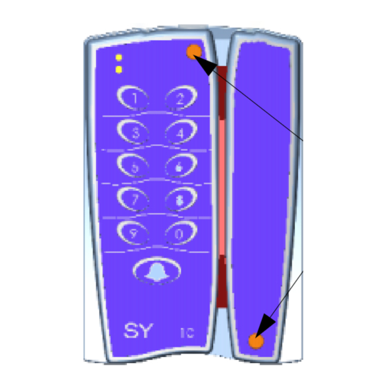
- Page 3 The PRX-40/A proximity reader-controller and SY-11 magnetic/barcode reader-controller access units are part of the compact access control - unit series manufactured by Synel. For the proximity unit, the card must be placed at a distance of about 10 cm from the device.
-
Page 4: Installation
Thus, the badge will receive maximal energy. PRX-40/A: • If you are installing more than one Synel reader, make sure the readers are installed at a distance of at least 50 cm from one another (a distance longer 5 times their reading limit). - Page 5 Replace the screw covers. PRX-40/A Mounting PRX-40 B. Remove Back Panel A. Open screw covers screws. Location of screws for option “B” fastening. Option “B” C. Drill holes Center hole Option “A” PRX-40 Back Bottom hole option Synel Industries Ltd.
-
Page 6: Connect Wires
Wire No. Wire Function Present Color Code Vin Power (Power Input) Red Black - TxRx RS-485 Grey + TxRx RS-485 Purple TxD RS -232 White RxD RS -232 Dark Green Alarm Brown Relay common (C) Blue Normally Closed (N.C) Yellow Synel Industries Ltd. - Page 7 Brown/White jumper JP23 settings Connector Description J4 (9 pin) Keyboard connector ISP J12 (6 pin) (programming the CPU slave) J13 (14 pin) Option for external reader (currently NA) How to connect the PRX-40/A to the Master controller: Synel Industries Ltd.
- Page 8 When JP9 is [2-3] ON, SEN 1.2, SEN 1.1 = Sensor AC Terminal Block - P3 Signal Description P3.1 Bell (1) P3.2 P3.3 Alarm P3.4 Ground P3.5 Transmit Data (RS-232) P3.6 Receive Data (RS-232) P3.7 -TXRX RS-485 P3.8 +TXRX RS-485 Synel Industries Ltd.
- Page 9 Reset for the slave/reader CPU- [2-3] closed [2-3] closed Programming of the slave/reader CPU [1-2] Closed 2.4.2. SY-11 Jumper Value Function Defaults Remarks Work Description Burn Position Magnetic Barcode option not in Barcode Tamper switch ON Tamper switch OFF Synel Industries Ltd.
- Page 10 Installation Stand-Alone Terminals Jumper Value Function Defaults Default Work Description Burn Position Stand alone Online Connect/ Termination resistor Disconnect Disconnect ON/OFF Spike/overvoltage protec- tion [1-2] [3-4] [2-3] Dry contact (DC) (Sensor) [1-2] [3-4] AC (Sensor) Synel Industries Ltd.
- Page 11 2 long beeps+2nd green led flashes Step 2. Enter the 8 digit master code (the default number is 12345678). Then insert the relevant set-up code (see next page). Note: Using the Clear key, you can go back to the previous stage! Synel Industries Ltd.
-
Page 12: Access Cards Configuration (Set-Up Codes)
Disabled Door opening time 000-255 In 1/10 seconds step 3 sec. (0 to 25.5 sec.) Alarm mode Latch (led is on) 1 = Led is off depend- ing on pulse time Pulse (led is off) (code 52) Synel Industries Ltd. - Page 13 Fingerprint (Operation- that consist of such a Mode 5): key). ----------------------- 1. Swipe card (2 beeps Mode 5 only with confirm swipe). PRintX * 2. Place finger Terminal reverts to 1. Delete card from Card list using card Synel Industries Ltd.
- Page 14 Type master code - 8 digits?? Initialisation of Master Code memory Delete all tem- Master code plates from finger Vocal ID indication Long buzzer for tens Short buzzer for unique numbers Reset alarm When the alarm is in latch Synel Industries Ltd.
- Page 15 7&8 simultaneously (mandatory) (press Enter in termi- nals that consist of such a key) in order to revert to normal mode. Using Card Build list: After entering set-up mode key-in code 20 (Insert card to list by card) and Synel Industries Ltd.
- Page 16 Card or code - Control is performed by Card or keying-in number of card (the length of the keyed-in number must be identical to the defined card length). Card and Global Code - Control is performed by Card and a common global Synel Industries Ltd.
-
Page 17: General Definitions
PRX-40/A After entering the “Programming Mode,” enter “60” to Erase All After entering the “Programming Mode,” enter “61” to initialize memory Note: Before starting teaching modes such as: 21,22,23 etc., it is strongly recommended to initialize memory! Synel Industries Ltd. - Page 18 000-255 time-out seconds. The alarm will be activated after the defined time-out. Duress code enable/disable Code 50--> 0 = Disable 1 = Enable In operation modes card and global code or card and pin code enables activating the alarm and the door simultaneously. Synel Industries Ltd.
- Page 19 2 digits Total characters Number of digits on card (when defining 00 - doesn’t check card length- accepts all card lengths upto 6) Reset alarm In set-up mode, after keying-in code 51, key-in 4 to shut-off the alarm. Synel Industries Ltd.
- Page 20 It is best to use a single cable for the communication line. If it is not possible to use a continues cable only one indoors connection is allowed, constructed in one of these options: Using two connectors with appropriate shielding and cover. Using a connection box. For aerial installation, use N.Y.Y. shielded cables. Synel Industries Ltd.
-
Page 21: Mechanical Features
Sensor Input: 9 -18V @ 10mA (in Non dry contact mode) • Power supply: 9 to 15 Vdc, max @ 100 mA. Door open request button - the entry will enable opening the door. Door sensor - the sensor will indicate that the door was forcefully opened. Synel Industries Ltd. -
Page 22: Appendix A - Fingerprint For Prx-40/A
Appendix A - Fingerprint for PRX-40/A PRintX40AI/V is a biometric stand-alone controller, one of the series of Synel’s access control protocols. It is a unit that operates with either a fingerprint verification version - PRintX40AV or a fingerprint identification version - PRintX40AI further to user-card reading (by the proximity unit). -
Page 23: Man-Machine Interface
Output relay rating: 24 V @ 3 A • Tamper sensor output TTL level max @ 16 mA Package • PRintX-40I_V proximity reader • PRintX biometric reader verification/identification • PRintX/P power supply adaptor: 5 Volt/1 A stabilized wide range input 100-240 AC input Synel Industries Ltd. - Page 24 Recommended: PRintX-40I_V Power supply adaptor:12 to 15 Vdc, max @ 880 mA Installation Front panel Note: When working with PRintX40A/I (Identification), you can install the PRintX on the external side of the door and the PRX40 on the internal side of the door. Synel Industries Ltd.
- Page 25 Stand-Alone Terminals Appendix A - Fingerprint for PRX-40/A Wiring Synel Industries Ltd.
-
Page 26: Maintenance
• Spill any liquids on the sensor with the exception of isopropyl alcohol. • Subject the fingerprint sensor to heavy shocks or vibrations. • Allow the sensor to come in contact with metallic objects. Synel Industries Ltd.
Need help?
Do you have a question about the PRX-40/A Proximity SY-11 and is the answer not in the manual?
Questions and answers