
Subscribe to Our Youtube Channel
Related Manuals for Schaub Lorenz SL0021KO

Summary of Contents for Schaub Lorenz SL0021KO
-
Page 1: Service Manual
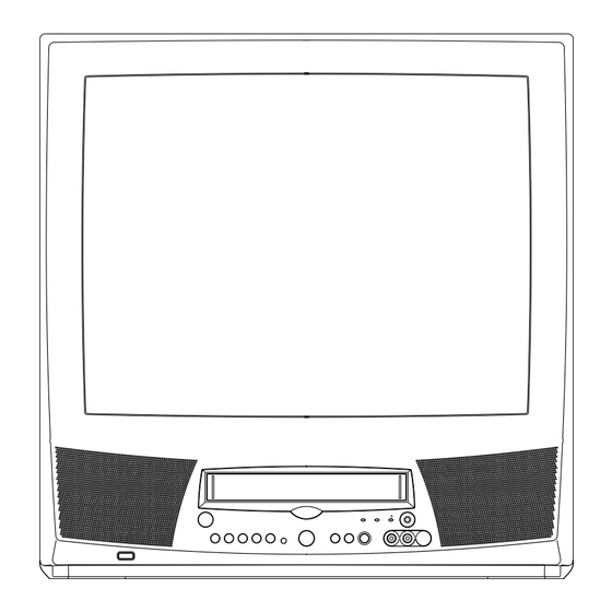
SL0021KO SERVICE MANUAL COLOR TELEVISION/VIDEO CASSETTE RECORDER ORIGINAL MFR’S VERSION A Design and specifications are subject to change without notice. -
Page 2: Table Of Contents
CONTENTS SERVICING NOTICES ON CHECKING ..................A1-1 HOW TO ORDER PARTS ......................A1-1 CONTENTS ..........................A2-1 GENERAL SPECIFICATIONS ....................A3-1~A3-5 DISASSEMBLY INSTRUCTIONS 1. REMOVAL OF MECHANICAL PARTS AND P. C. BOARDS ..........B1-1, B1-2 2. REMOVAL OF DECK PARTS .................... B2-1~B2-5 3. -
Page 3: General Specifications
GENERAL SPECIFICATIONS CRT Size / Visual Size 21 inch / 508.0mmV System CRT Type Normal Deflection degree Magnetic Field BV/BH +0.45G/0.18G Color System Speaker 1Speaker Position Front Size 3 Inch Impedance 8 ohm Sound Output 2.5W 10%(Typical) 2.0W System System Player / Recorder Video System Hi-Fi STEREO... - Page 4 GENERAL SPECIFICATIONS at DC Stand by (at AC) 6 W at 230 V 50 Hz Per Year Protector Power Fuse Dew Sensor Regulation Safety Radiation X-Radiation Temperature Operation C ~ +40 Storage C ~ +60 Operating Humidity Less then 80% RH On Screen Menu Display...
- Page 5 GENERAL SPECIFICATIONS No Operation min. Timer Back-up (at Power Off Mode) min. G-12 Remote Unit RC-CH Control Glow in Dark Remocon Power Source Voltage(D.C) UM size x pcs UM-4 x 2 pcs Total Keys Keys Keys Power 0/AV CH/Tr Up CH/Tr Up/Page Up CH/Tr Down CH/Tr Down /Page Down...
- Page 6 GENERAL SPECIFICATIONS Auto Repeat VIDEO PLUS+(SHOWVIEW,G-CODE) CH Auto Set-Up/Auto Clock Forward / Reverse Picture Search One Touch Playback Auto Tuning Anti-Theft End Call Index Search SQPB CATV CM Skip(30sec x 6 Times) Comb Filter T'Text Text type Unitext Scene Repeat Hotel Lock TV Monitor TV/Rec Monitor...
- Page 7 GENERAL SPECIFICATIONS Rec/OTR T-Rec On Timer Key Light up Rec/OTR One Touch Playback Play Terminals Front Video Input RCA x1 Audio Input RCA x1 Other Terminal Head Phone(Stereo & Mono, 3.5mm) Rear Video Input Audio Input Video Output Audio Output Euro Scart 1-SCART Diversity...
-
Page 8: Disassembly Instructions
DISASSEMBLY INSTRUCTIONS 1. REMOVAL OF MECHANICAL PARTS 1-3: TV/VCR BLOCK (Refer to Fig. 1-3) Remove the 2 screws 1. AND P.C. BOARDS Disconnect the following connectors: 1-1: BACK CABINET (Refer to Fig. 1-1) (CP302, CP351, CP757, CP401, CP501 and CP502). Remove the 6 screws 1. - Page 9 DISASSEMBLY INSTRUCTIONS 1-5: DECK SHIELD PLATE (Refer to Fig. 1-5) Remove the 2 screws 1. Remove the 4 screws 2. Remove the screw 3. Remove the Deck Shield Plate in the direction of arrow (A). Remove the screw 4. Remove the Shield Plate Bottom in the direction of arrow (B). Deck Chassis Deck Shield Plate Syscon PCB...
-
Page 10: Removal Of Deck Parts
DISASSEMBLY INSTRUCTIONS 2. REMOVAL OF DECK PARTS NOTE When you install the Tape Guide L, install as shown in the 2-1: TOP BRACKET (Refer to Fig. 2-1) circle of Fig. 2-3-B. (Refer to Fig. 2-3-B) Remove the 2 screws 1. Slide the 2 supports 2 and remove the Top Bracket. - Page 11 DISASSEMBLY INSTRUCTIONS 2-6: LINK ASS'Y (Refer to Fig. 2-6) 2-9: TENSION ASS'Y (Refer to Fig. 2-9-B) Set the Link Ass'y to the Eject position. Turn the Middle Gear clockwise so that the Tension Remove the (A) side of the Link Ass'y first, then remove Holder hook, is set to the position of Fig.
- Page 12 DISASSEMBLY INSTRUCTIONS 2-10: T BRAKE ASS'Y (Refer to Fig. 2-10) Remove the T Brake Spring. P5 Spring Turn the T Brake Ass'y clockwise and bend the hook Cassette Opener section to remove it. P5-3 Arm Ass'y Pinch Roller Block T Brake Ass'y Pinch Roller Arm Spring Hook section Pinch Roller Lever Ass'y...
- Page 13 DISASSEMBLY INSTRUCTIONS Capstan Belt Capstan DD Unit Spring Position Fig. 2-13-B 2-14: FE HEAD (RECORDER ONLY) (Refer to Fig. 2-14) Remove the screw 1. Remove the FE Head. • Screw Torque: 5 ± 0.5kgf•cm Fig. 2-16 FE Head 2-17: MIDDLE GEAR/MAIN CAM (Refer to Fig. 2-17-A) Remove the Polyslider Washer 1, then remove the Middle Gear.
- Page 14 DISASSEMBLY INSTRUCTIONS 2-18: CLUTCH ASS'Y (Refer to Fig. 2-18) NOTES Remove the Capstan Brake Spring. 1. When you install the Loading Arm S Ass'y, Loading Arm Remove the Polyslider Washer 1. T Ass'y and Main Loading Gear, align each marker. Remove the Clutch Ass'y, Ring Spring and Coupling (Refer to Fig.
-
Page 15: Removal Of Anode Cap
DISASSEMBLY INSTRUCTIONS 3. After one side is removed, pull in the opposite direction to 3. REMOVAL OF ANODE CAP remove the other. Read the following NOTED items before starting work. NOTE After turning the power off there might still be a potential Take care not to damage the Rubber Cap. -
Page 16: Removal And Installation Of Flat Package Ic
DISASSEMBLY INSTRUCTIONS REMOVAL AND INSTALLATION OF When IC starts moving back and forth easily after desoldering completely, pickup the corner of the IC using FLAT PACKAGE IC a tweezers and remove the IC by moving with the IC desoldering machine. (Refer to Fig. 4-3.) REMOVAL NOTE Put the Masking Tape (cotton tape) around the Flat... - Page 17 DISASSEMBLY INSTRUCTIONS INSTALLATION When bridge-soldering between terminals and/or the soldering amount are not enough, resolder using a Thin- Take care of the polarity of new IC and then install the tip Soldering Iron. (Refer to Fig. 4-8.) new IC fitting on the printed circuit pattern. Then solder each lead on the diagonal positions of IC temporarily.
-
Page 18: Key To Abbreviations
KEY TO ABBREVIATIONS Audio/Control H.SW Head Switch Automatic Color Control Hertz Audio Erase Integrated Circuit Automatic Frequency Control Intermediate Frequency Automatic Fine Tuning Indicator AFT DET Automatic Fine Tuning Detect Inverter Automatic Gain Control Killer Amplifier Left Antenna Light Emitting Diode A.PB Audio Playback LIMIT AMP... - Page 19 KEY TO ABBREVIATIONS SYNC Synchronization SYNC SEP Sync Separator, Separation Transistor TRAC Tracking TRICK PB Trick Playback Test Point UNREG Unregulated Volt Voltage Controlled Oscillator Video Intermediate Frequency Vertical Pulse, Voltage Display V.PB Video Playback Variable Resistor V.REC Video Recording Visual Search Fast Forward Visual Search Rewind Voltage Super Source...
-
Page 20: Service Mode List
SERVICE MODE LIST This unit provided with the following SERVICE MODES so you can repair, examine and adjust easily. To enter SERVICE MODE, unplug AC cord till lost actual clock time. Then press and hold Vol (-) button of main unit and remocon key for more than 2 seconds. -
Page 21: Preventive Checks And Service Intervals
PREVENTIVE CHECKS AND SERVICE INTERVALS The following standard table depends on environmental conditions and usage. Unless maintenance is properly carried out, the following service intervals may be quite shortened as harmful effects may be had on other parts. Also, long term storage or misuse may cause transformation and aging of rubber parts. Time 1,000 1,500... - Page 22 PREVENTIVE CHECKS AND SERVICE INTERVALS CLEANING NOTE 2. TAPE RUNNING SYSTEM After cleaning the heads with isopropyl alcohol, do not When cleaning the tape transport system, use the run a tape until the heads dry completely. If the heads gauze moistened with isopropyl alcohol. are not completely dry and alcohol gets on the tape, 3.
-
Page 23: When Replacing Eeprom (Memory) Ic
WHEN REPLACING EEPROM (MEMORY) IC If a service repair is undertaken where it has been required to change the MEMORY IC, the following steps should be taken to ensure correct data settings while making reference to TABLE 1. NOTE: Initial Data setting will not be possible if clock has been set. To reset clock, either unplug AC cord and allow at least 30 minutes before Power On. -
Page 24: Servicing Fixtures And Tools
SERVICING FIXTURES AND TOOLS (For 2 head 1 speed model, (For 2 head 2 speed model) JG002B Adapter JG005 Post Adjustment 4 head model) VHS Alignment Tape JG002E Dial Torque Gauge Screwdriver VHS Alignment Tape JG001C (VP S-LI6 ) (10~90gf•cm) Part No. -
Page 25: Preparation For Servicing
PREPARATION FOR SERVICING How to use the Servicing Fixture Unplug the connector CP351, CP757 and CP302 then remove the TV/VCR Block from the set. Unplug the connector CP810, CP820 and CP850, then remove the Main PCB from the VCR Block. Connect as shown in the below figure using the Service Fixture. -
Page 26: Mechanical Adjustments
MECHANICAL ADJUSTMENTS 1. CONFIRMATION AND ADJUSTMENT 1-2: CONFIRMATION AND ADJUSTMENT OF TENSION POST POSITION Read the following NOTES before starting work. Set to the PLAY mode. • Place an object which weighs between 450g~500g on Adjust the Tension Adjust until the edge of the Tension the Cassette Tape to keep it steady when you want to Arm is positioning within 0.5mm range from the make the tape run without the Cassette Holder. - Page 27 MECHANICAL ADJUSTMENTS 1-4: CONFIRMATION OF VSR TORQUE NOTE Install the Torque Gauge (JG002F) and Adapter (JG002B) If the torque is out of the range, replace the following on the S Reel. Set to the Picture Search (Rewind) mode. parts. (Refer to Fig.1-4) Check item Replacement Part Then, confirm that it indicates 120~180gf•cm.
- Page 28 MECHANICAL ADJUSTMENTS 2-2: CONFIRMATION AND ADJUSTMENT OF AUDIO/ 2-3: TAPE RUNNING ADJUSTMENT CONTROL HEAD (X VALUE ADJUSTMENT) When the Tape Running Mechanism does not work well, Confirm and adjust the height of the Reel Disk. adjust the following items. (Refer to item 1-1) Confirm and adjust the position of the Tension Post.
- Page 29 MECHANICAL ADJUSTMENTS 3. MECHANISM ADJUSTMENT PARTS LOCATION GUIDE 1. Tension Adjust X value adjustment driver hole 2. Tension Arm P4 Post 3. Guide Roller T Brake Spring 4. P1 Post T Reel 5. Audio/Control Head S Reel D1-4...
-
Page 30: Electrical Adjustments
ELECTRICAL ADJUSTMENTS 1. ADJUSTMENT PROCEDURE Read and perform these adjustments when repairing the CH-2 circuits or replacing electrical parts or PCB assemblies. CAUTION When replacing IC's or transistors, use only specified 6.5H silicon grease. (YG6260M) (To prevent the damage to IC's and transistors.) CH-1 Fig. - Page 31 ELECTRICAL ADJUSTMENTS (TV SECTION) 2-8: HORIZONTAL PHASE Receive the center cross signal from the Pattern 2-4: CONSTANT VOLTAGE Generator. Connect the digital voltmeter to TP401. Using the remote control, set the brightness and Set condition is AV MODE without signal. contrast to normal position.
- Page 32 ELECTRICAL ADJUSTMENTS 2-11: VERTICAL LINEALITY 1. BRIGHT NOTE: Adjust after performing adjustments in section 2-10. 2. CONTRAST Receive the cross hatch signal from the Pattern 3. COLOR Generator. 4. TINT Using the remote control, set the brightness and 5. SHARPNESS contrast to normal position.
- Page 33 ELECTRICAL ADJUSTMENTS 2-17: SUB SHARPNESS Activate the adjustment mode display of Fig. 1-1 and press the channel button (04) on the remote control to select "PICTURE". The Fig. 2-6 appears on the display. Press the channel button (05) on the remote control to select "SHARPNESS".
- Page 34 ELECTRICAL ADJUSTMENTS 3. ELECTRICAL ADJUSTMENT PARTS LOCATION GUIDE (VCR SECTION) TP1001 TP4002 TP4001 IC601 TU601 L608 CP603 J4501 TP4501 SYSCON PCB D2-5...
- Page 35 ELECTRICAL ADJUSTMENTS (TV SECTION) J801 TP801 CRT PCB VR502 T501 FOCUS VOLUME FB401 SCREEN VOLUME TP401 MAIN PCB D2-6...
-
Page 36: Purity And Convergence
ELECTRICAL ADJUSTMENTS PURITY AND CONVERGENCE 4-3: STATIC CONVERGENCE ADJUSTMENTS NOTE Adjust after performing adjustments in section 4-2. NOTE Receive the crosshatch pattern from the color bar Turn the unit on and let it warm up for at least 30 generator. minutes before performing the following adjustments. -
Page 37: Y/C/Audio/Head Amp/21Pin/In/Out
V. OUTPUT IC TV BLOCK DIAGRAM IC401 AN5539N THERMAL PROTECTION PUMP SOUND AMP IC IC352 AN7523 Q353, Q351 A_MUTE SW SP351 SPEAKER Q405 Q406 J351 H-DRIVE H. OUTPUT HEADPHONE_JACK X601 CHROMA/IF IC 4.433619MHz IC601 FB401 LA76812 T' TEXT SYNC CLMP J801 Q607 BUFFER... -
Page 38: Micon/Jack/Led
Y/C/AUDIO/HEAD AMP/21PIN/IN/OUT BLOCK DIAGRAM Q4010 X4001 4.433619MHz Y/C/AUDIO/ BUFFER CCD/HEAD AMP IC IC4001 HA118217F CP4001 6dB AMP 6dB AMP SP-CH2 (L) 2MLPF C CCD CTL TRAP CYL. SP_COM fh HPF CLEAR C SQUELCH SP-CH1 (R) SYNC DELAY CLPF N-->P 2FSC_A CLOCK TRAP CLPH... - Page 39 MICON/JACK/LED BLOCK DIAGRAM SW1001 SYSCON/TIMER/SERVO IC IC1006 OEC0094B SYSTEM RESET IC IC1002 /RES 3 OUT TAB_SW RE5VS31A POWER_FAIL POWER_FAIL (DC) AT+5.6V MS SEN-A EXT_IN-L EXT_IN_L MS_SEN A Q1009 TUNER MUTE TU_AUDIO_MUTE_H 4/2FSC IN 2FSC_A MS SEN_B MS_SEN B C.SYNC V. SYNC Q1003 VCR_MUTE VCR_A_MUTE...
- Page 40 T' TEXT BLOCK DIAGRAM Y/C_VIDEO D860 Q863 21_B P.CON+5V V. REF Y/C/AUDIO/ D858 HEAD AMP/ 21_R 21PIN/IN/OUT D855 21_G D852 D857 21_Y D859 TRIPLE ANALOG MPXER IC IC853 D856 Q856 TC74HC4053AF BUFFER DATA SLICER IC DECODER IC IC852 IC851 ET106 ET317 Q855 BUFFER...
- Page 41 Y/C/AUDIO/HEAD AMP SCHEMATIC DIAGRAM (SYSCON PCB) L4002 W820 BUFFER Q4010 100uH 2SC2412K 0607 BUFFER Q4006 W803 FROM/TO CHROMA/IF Y/C_VIDEO 2SA1037AK TU_VIDEO R4040 TU_AUDIO 100 1/4W FROM POWER Y/C_VIDEO Y/C_AUDIO Q4007 R4055 2SC2412K Y/C_AUDIO W905 V.ENV L4008 R4053 R4054 TP4002 FROM 21PIN IN/OUT P.CON+9V JWF-50K-1 560K...
-
Page 42: Micon
MICON SCHEMATIC DIAGRAM (SYSCON PCB) R1096 FROM/TO Y/C/AUDIO/HEAD AMP D1006 FROM/TO POWER TRICK_PB_H D1010 SB10-03A3 C1030 VCR_A_MUTE AT+5.6V SB10-03A3 H.SW 0.1 F V.SYNC VCR_POWER_H X1001 R1074 P.CON+5V 100CT AT+12V 01002 (LDM) 2FSC_A MOTOR_GND MESECAM_M C1060 D.V_SYNC 0.1 B V.REC_ST_H 5.0 5.2 5.2 3.3 2.5 0 2.5 5.2 1.4 1.5 0 4.9 5.1 5.2 5.2 5.2 5.2 5.2 0 5.1... -
Page 43: Power
POWER SCHEMATIC DIAGRAM (SYSCON PCB) P.CON+5V_B TO Y/C/AUDIO/HEAD AMP P.CON SW P.CON+9V Q1010 2SD734 P.CON+5V 5V REG. IC IC1005 KIA7805API FROM/TO MICON 9V REG IC VCR_POWER_H IC1003 KIA7809API AT+5.6V AT+12V P.CON+5V MOTOR_GND HS1001 763WAE0108 AT+5.6V TO CHROMA/IF FROM TV POWER 12.0 P.CON+9V AT+5.6V... - Page 44 21PIN/IN/OUT SCHEMATIC DIAGRAM (SYSCON PCB) FROM/TO SOUND AMP FROM/TO MICON SOUND_GND_A SOUND+ KEY_B W894 SP_OUT REC_LED T-REC_LED KEY_A FROM POWER D4202 AT+5.6V REMOCON_IN W822 11ES1N STANDBY_H P.CON+5V TUNERON/OFF-A POWER ON SW VV-H Q4201 EXT_IN_L DTC114EK TU_AUDIO_MUTE_H OS1001 R1102 R1103 R1104 R1105 R1109 R1106...
-
Page 45: Chroma/If
CHROMA/IF SCHEMATIC DIAGRAM FROM/TO MICON SD-L/AFC-OFF-H (SYSCON PCB) VV-H TEXT_Y VCR_POWER_H TV_POWER_H R.OUT G.OUT B.OUT POWER_FAIL[DC] DEGAUSS_H C663 M.POWEROFFMUTE_H TO SOUND AMP 6.3V V.REF R614 TUNER_AGC Q602 2SC2412K AUDIO_OUT SOUND_GND H.OUT SW H.OUT SW IIC_OFF Q603 Q604 SOUND+B R647 AFT_M DTC114EKA DTC114EKA P.CON+5V_B... -
Page 46: Sound Amp
SOUND AMP SCHEMATIC DIAGRAM (SYSCON PCB) SOUND AMP IC IC352 AN7523 C360 C361 0.001 B A_MUTE SW Q353 2SC2412K FROM/TO 21PIN IN/OUT SPEAKER CP302 B2B-EH-A SP_OUT SP_OUT C363_1 SOUND_GND SOUND+ 1000 8_OHM SP351 SOUND_GND_A P-300S-3-6 FROM MICON W953 C362_1 M.POWEROFFMUTE_H R308 10K 1/4W R353... - Page 47 T’TEXT SCHEMATIC DIAGRAM (SYSCON PCB) FROM Y/C/AUDIO/HEAD AMP Y/C_VIDEO L854 FROM MICON 100uH TEXT_RESET W801 AT+5.6V_A BUFFER Q856 D854 TO CHROMA/IF 2SC2412K SB10-03A3 SYNC L851 FROM POWER V.REF 10uH AT+5.6V Q863 P.CON+5V 2SC2412K R861 D855 1SS133 R869 SYNC BUFFER D858 W952 C857 Q853...
- Page 48 TV POWER SCHEMATIC DIAGRAM (MAIN PCB) DEGAUSS_H FROM/TO DEFLECTION RELAY DRIVE Q504 SOUND+B D516 2SC1815Y TV.POWER_H 1SS133 DEGAUSS_H P.CON+125V POWER_FAIL AT+125V VCR.POWER_H RY501 SOUND_GND SDT-S-112LMR DEGAUSS COIL R517_1 L503 C516 W829 8H200015 CP502 500V 470P 2.2 2W TV-50P-02-A1 D505 SOUND+B 21DQ09N TH501 D509...
- Page 49 DEFLECTION SCHEMATIC DIAGRAM (MAIN PCB) V.OUTPUT IC IC401 AN5539N THERMAL PROTECTION PUMP UP TO DY CP401 14.6 25.4 24.8 TS-80P-04-V1 W805 FROM/TO CHROMA/IF CP820_1 (CP502) 8283_1312_00_000 SOUND +B SOUND_GND C412 H.OUT 500V 390P R427 R425 P.CON+5V 5.6K 4.7K W826 V.OUT R413_1 R412 R416...
-
Page 50: Crt
CRT SCHEMATIC DIAGRAM (CRT PCB) FROM CHROMA/IF TP801 CP850 (CD850) R802 8283_0512_00_000 15K 2W R807 CUT_OFF G.OUT 132.5 2.7K 1/4W R.OUT RED AMP B.OUT Q804_1 2SC4217 TP802 104.1 R808 132.5 2.7K 1/4W 132.8 C809 560P B R811 J801 CVT3275-5102 R805 15K 2W 132.1 GREEN AMP... -
Page 51: Jack/Led
JACK/LED SCHEMATIC DIAGRAM (OPERATION PCB) HEADPHONE JACK J351 HTJ-035-28A R350 R351 33 1/2W 33 1/2W W805 FROM/TO 21PIN/IN/OUT (CP353) (CP4202) CD351_1 CH274101 FRONT_VIDEO_IN FRONT_A_IN_L L004 GND/SOUND GND W5T18.4X10X9.6 SOUND_OUT_L SP_OUT_L POWER/PLAY R761 270 1/4W D792 SLZ-936C-07-S-T1 FROM 21PIN/IN/OUT VIDEO AUDIO L FRONT AV JACK (CP354) (CP352) -
Page 52: Deck
DECK SCHEMATIC DIAGRAM (DECK PCB) LOADING MOTOR M101 S105 BOT SENSOR S106 Q101 RPT-38PB113 S101 S102 S103 S104 FROM/TO MICON CP101 52044-0445 LDM- LDM+ PCB550 VE8851 CAUTION: SINCE THESE PARTS MARKED BY ATTENTION: LES PIECES REPAREES PAR UN ETANT NOTE: NOTE: THIS SCHEMATIC DIAGRAM IS THE LATEST AT THE TIME THE DC VOLTAGE AT EACH PART WAS CRITICAL FOR SAFETY,USE ONES... -
Page 53: Interconnection Diagram
INTERCONNECTION DIAGRAM HEADPHONE_JACK J351 VIDEO AUDIO L FRONT AV JACK HALL MAIN ROTOR J701_1 SENSOR COIL MAGNET FG SENSOR OPERATION PCB PCB030 TE9A16 S101 S102 L351 L757 HALL HALL SWITCH LOGIC CP1004 AC230V_50Hz CP302 CD501_1 SPEAKER CP504 MOTOR_GND SP_OUT BLUE I_LIMIT SOUND_GND 8 OHM... - Page 54 WAVEFORMS Y/C/AUDIO/HEAD AMP TV POWER 11 PB 6 20V 20µs/div 1 5V 0.1ms/div 2V 10ms/div DEFLECTION 2 5V 50µs/div 7 20V 20µs/div 12 PB 10mV 5ms/div DEFLECTION 8 10V 10ms/div 3 0.5V 10ms/div 13 POWER ON 200mV 50ns/div TV POWER 9 20V 10ms/div 14 POWER ON 4 200mV 50µs/div...
- Page 55 WAVEFORMS MICON 21 POWER ON 16 POWER ON 26 PB 200mV 10µs/div 1V 50ns/div 50mV 0.5ms/div 17 POWER ON 22 POWER ON 27 PB 50mV 1ms/div 1V 20µs/div 1V 0.5µs/div 23 POWER ON 18 POWER ON 28 PB 50mV 1ms/div 2V 20µs/div 1V 0.5µs/div 19 REC...
- Page 56 WAVEFORMS 21PIN/IN/OUT 31 POWER ON 36 POWER ON 41 POWER ON 0.5V 10µs/div 0.5V 20µs/div 200mV 0.1µs/div 32 POWER ON 42 POWER ON 37 POWER ON 20mV 1ms/div 200mV 10µs/div 0.5V 20µs/div CHROMA/IF 33 POWER ON 38 POWER ON 43 POWER ON 5mV 1ms/div 0.5V 10ms/div 10mV 10µs/div...
-
Page 57: Waveforms
WAVEFORMS SOUND AMP 46 REC 0.5V 0.5ms/div T' TEXT POWER ON 200mV 50ns/div NOTE: The following waveforms were measured at the point of the corresponding balloon number in the schematic diagram.
Need help?
Do you have a question about the SL0021KO and is the answer not in the manual?
Questions and answers