Table of Contents
Advertisement
Advertisement
Table of Contents

Related Manuals for Odom Echotrac CV100

Summary of Contents for Odom Echotrac CV100
- Page 1 ECHOTRAC CV100 USER MANUAL Version: 4.04 Odom Hydrographic Systems, Inc. 1450 Seaboard Avenue Baton Rouge, Louisiana 70810-6261 Telephone: (225) 769-3051 Fax: (225) 766-5122 Email@Odomhydrographic.com http://www.odomhydrographic.com Number of pages: 43 Date: May 28, 2008...
- Page 2 4.00 02-19-2008 P. Oostenrijk Updated Odom Title and Logo on cover page. Updated Header and Footer according to new template. Updated the introduction section and listed major changes. Inserted screen capture of new dialog for selecting a sounders on the network.
-
Page 3: Table Of Contents
Known problems with Transducer......................21 Technical specifications ..........................23 Computer communications ........................23 Overview Serial Output string formats ...................... 24 Serial output strings ..........................26 6.3.1 Echotrac SBT............................. 26 6.3.2 Echotrac DBT............................. 27 Page 3 of 3 Odom Hydrographic Systems, Inc. May 28, 2008... -
Page 4: Odom Hydrographic Systems, Inc Page 4 Of
Serial 3 ..............................39 Heave ................................ 39 LAN ................................39 Transducer ..............................40 DC ................................40 Appendix A. CABLE CONNECTIONS: ......................... 41 Appendix B. Quick Start Operating Procedures ....................42 Page 4 of 4 Odom Hydrographic Systems, Inc. May 28, 2008... -
Page 5: Introduction
1 INTRODUCTION There are four Echotrac CV units named Echotrac CV100, Echotrac CV200, Echotrac CV300 and Echotrac CVM (Mobile). This document covers the Echotrac CV100 and will refer to this unit as “Echotrac CV”. This Echotrac CV supports one channel. -
Page 6: Purpose
2007-02-27 Title: Using Echotrac Ethernet Driver with Hypack Author(s): Stephen Apsey Report no: Version: Date: 2006-07-17 Title: Technical Specification Ethernet Interface Author(s): Patrick Oostenrijk Report no: Version: Date: 2008-05-28 Page 6 of 6 Odom Hydrographic Systems, Inc. May 28, 2008... -
Page 7: Product Description
1370 – 1700 m/s • Dimensions Resolution 1 m/s • 28cm (11”) x 23cm (9”) W x Transducer Draft Setting • 11.5cm (4.5”) D 0 – 15m (0 – 50 ft.) Page 7 of 7 Odom Hydrographic Systems, Inc. May 28, 2008... -
Page 8: Overview
Should the DC input voltage polarity be applied in reverse, an audible alarm within the unit will sound regardless of the POWER switch setting. In the event that the input voltage drops below the minimum threshold the unit will automatically shut down. Page 8 of 8 Odom Hydrographic Systems, Inc. May 28, 2008... -
Page 9: Choice Of Operating Frequencies
(See 2.1 Specifications). 2.6 Signal connector Transducer The signal from the transducer is passed to the Echotrac CV via a standard Odom transducer cable with a twist- lock connector. Page 9 of 9 Odom Hydrographic Systems, Inc. -
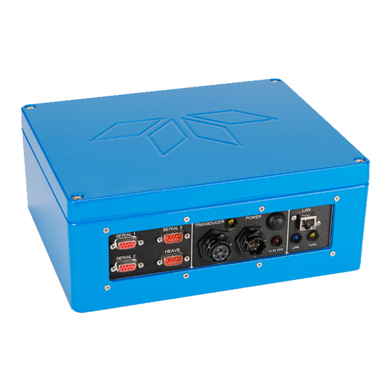
Page 10: Serial Ports
When the Echotrac CV is turned on, a red LED will be on to indicate that the internal systems have powered up successfully. The red LED is located below the power button. Page 10 of 10 Odom Hydrographic Systems, Inc. May 28, 2008... -
Page 11: Ethernet Indicators
The Transmit indicators on the Echotrac CV indicate whether the Transducer is firing or not. The frequency at which the Channel indicator flickers also indicates whether the Transducer is firing at a slow or fast pace. Page 11 of 11 Odom Hydrographic Systems, Inc. May 28, 2008... -
Page 12: Installation
See also the quick start procedure in Appendix B. 3.1 Software installation Odom eChart, also referred to as the Echotrac Control program, is used to communicate with the Echotrac CV. The manual for Odom eChart explains the installation procedure. -
Page 13: Powering Up The Equipment
Note: Should you feel that a return to the sounder’s default parameter values is called for, then select the Default Reset option in the Echotrac CV Window Application program. Page 13 of 13 Odom Hydrographic Systems, Inc. May 28, 2008... -
Page 14: Transducer Installation
The fairing has the dual effect of both minimizing possible strike damage and smoothing the flow of water over the face of the transducer. Figure 4: Transducer mounted through the hull Page 14 of 14 Odom Hydrographic Systems, Inc. May 28, 2008... -
Page 15: Sea Chest" Transducer Installation
"sea chest" design in order to provide hydrostatic pressure equalization. Transducer cables generally leave these assemblies through stuffing tubes, which maintain the watertight integrity of the chest. Page 15 of 15 Odom Hydrographic Systems, Inc. May 28, 2008... -
Page 16: Over-The-Side" Transducer Installation
In all of the above installations, particular care should be taken to assure that the transducer radiating face remains as parallel to the water surface as much as possible while the vessel is moving. Page 16 of 16 Odom Hydrographic Systems, Inc. May 28, 2008... -
Page 17: Operational Procedures
- Elapsed time measured from the transducer to the bottom and back to the transducer. - Index constant. - Distance from the referenced water surface to the transducer (draft). Page 17 of 17 Odom Hydrographic Systems, Inc. May 28, 2008... - Page 18 This will force the digitizer to only detect returns from the Bar. See section 4.3 on how to perform a bar-check. Page 18 of 18 Odom Hydrographic Systems, Inc. May 28, 2008...
-
Page 19: How To Perform A Bar Check
Draft + Index Bar depth Transducer Bar gate width The figure above shows that the bar is placed under the transducer and kept at a certain measured depth using cables. Page 19 of 19 Odom Hydrographic Systems, Inc. May 28, 2008... -
Page 20: Shallow Water Operation
Blanking which is deeper than the false return. This will force the digitizer to lock to the bottom. If the Echotrac is connected to an external computer/data logger, confirm that correct digitized depths are being transferred. Page 20 of 20 Odom Hydrographic Systems, Inc. May 28, 2008... -
Page 21: Troubleshooting
5.2 The Echotrac CV power LED is off Try powering the Echotrac CV down and back up again. If this does not resolve the problem, contact Odom Hydrographic Systems, Inc. for assistance. 5.3 The Echotrac CV power LED is flickering Reduce the Transmit power. - Page 22 Echotrac CV100 User Manual TRANSDUCER FACE Air trapped under a thin film layer on the face of the transducer. Page 22 of 22 Odom Hydrographic Systems, Inc. May 28, 2008...
-
Page 23: Technical Specifications
The following section of this chapter shows an overview of all the output strings and their formats, followed by detailed information about the output string structures. Page 23 of 23 Odom Hydrographic Systems, Inc. May 28, 2008... -
Page 24: Overview Serial Output String Formats
Therefore, if the depth for all three channels are being output, and all three have errors, then Channel 1 has the highest priority and its error letter will be shown in the output. Not either of the other two channels because they have a lower priority. Page 24 of 24 Odom Hydrographic Systems, Inc. May 28, 2008... - Page 25 If multiple channels are in use and not all the channels have an error, then priority of the channels determines which letter is displayed to indicate the Error. If all channels are used and all have an Error, a unique letter is used to identify that situation. Page 25 of 25 Odom Hydrographic Systems, Inc. May 28, 2008...
-
Page 26: Serial Output Strings
Low), the SBT string is output until another string is selected in the Communications menu. When SBT is selected, but the unit is operating in dual frequency, the High frequency depth is output. Page 26 of 26 Odom Hydrographic Systems, Inc. May 28, 2008... -
Page 27: Echotrac Dbt
Please note that characters 2 & 3 are in upper case whenever the Units are in tenths of feet, and are in lower case when the units are in centimeters. Example: <sp>ETOL<sp>DDDDD<CR> Page 27 of 27 Odom Hydrographic Systems, Inc. May 28, 2008... - Page 28 Please note that characters 2 & 3 are in upper case whenever the Units are in tenths of feet, and are in lower case when the units are in centimeters. Example: FetDB<sp>DDDDD<sp>DDDDD<CR> Page 28 of 28 Odom Hydrographic Systems, Inc. May 28, 2008...
-
Page 29: Heave
+ or - Heave Direction 19, 20,21.22 HHHH Heave Data (x.xx) Always Centimeter Resolution Carriage Return Example: FET<sp>B<sp><sp><sp>184<sp><sp><sp>193+1234<CR> ; Fix Mark, Dual Freq., 18.4FT for High, 19.3 for Low, +12.34m heave Page 29 of 29 Odom Hydrographic Systems, Inc. May 28, 2008... -
Page 30: Deso25
Line Feed DESO DDV Draft Character # Character Description Always D Always G Draft Data Period Draft Data decimal <sp> Space “m” indicates meters <sp> Space Carriage Return Line Feed Page 30 of 30 Odom Hydrographic Systems, Inc. May 28, 2008... -
Page 31: Deso Commands
Depth in meters. Single decimal floating point number. Depth in fathoms. Single decimal floating point number. 8 bit hexadecimal value checksum calculated over the entire string excluding the leading ‘$’ Carriage return Line Feed Example: $SDDBS,29.1,f,8.9,M,4.8,F*36<CR><LF> Page 31 of 31 Odom Hydrographic Systems, Inc. May 28, 2008... -
Page 32: Serial Data Input / Chart Annotation
After the last "CR", send the HEX 04 delimiter to return ECHOTRAC to normal operation. (In order to advance blank paper, send the HEX 0D ("CR") as many times as necessary.) Page 32 of 32 Odom Hydrographic Systems, Inc. May 28, 2008... -
Page 33: Serial Heave Input
Heave data Status flag <sp>,- Space if positive, minus if negative 16-19 Roll data <sp> Space <sp>,- Space if positive, minus if negative 22-25 Pitch data Carriage Return Line Feed Page 33 of 33 Odom Hydrographic Systems, Inc. May 28, 2008... -
Page 34: External Serial Control Of Echotrac Parameters
VELOCITY identified by the parameter number 08 was changed to a new value of 1464 m/s. The string delimiter (CR) will always terminate the input. Use Control T (HEX 14) to stop the chart and Control R (HEX 12) to restart the chart. Page 34 of 34 Odom Hydrographic Systems, Inc. May 28, 2008... - Page 35 Also, as of version 3.06 the ID used to request a parameter value changed from 86 to 187. Firmware Request ID 3.01 – 3.05 3.06 – See chapter 7 Overview parameters and settings for a table listing all the parameters and their unique identifier. Page 35 of 35 Odom Hydrographic Systems, Inc. May 28, 2008...
-
Page 36: Overview Parameters And Settings
The Echotrac ETHERNET port runs at 10 Mbps and outputs 16 or 8 bit samples of the acoustic data. The ETHERNET port also sends out all parameters . See reference [3] for more details. Page 36 of 36 Odom Hydrographic Systems, Inc. May 28, 2008... -
Page 37: Uploading Firmware
2-To upgrade the Motorola processors you need the new binary file. The file is named ECV1COM.bin and must be obtained from Odom Hydrographic Systems Inc.. We normally do not put these on our web site, but we can email them to you or they will be sent on a CD disk. Once these files have been obtained put them in a known folder in the computer with the Odom Flash Program. -
Page 38: Upgrading Dsp Firmware
Upgrading of the firmware requires a special serial cable that can be ordered from Odom Hydrographic Systems, Inc. The firmware for the DSPs is not on our web site so it needs to be obtained by email or sent on a disk. -
Page 39: Echotrac Cv Cable Connections
Data from the motion sensoro the Echotrac MKIII 9.5 LAN The LAN connection is the Ethernet port for the Echotrac. Connector PN: Pin Number Signal Description 10BASE-T TX + TX - RX + RX - Page 39 of 39 Odom Hydrographic Systems, Inc. May 28, 2008... -
Page 40: Transducer
Echotrac CV100 User Manual 9.6 Transducer If using Odom Hydrographic Systems, Inc. normal dual frequency transducer or a signal frequency transducer connect the transducer here. Connector PN: Pin Number Signal Description MS3116J14-5P Shield High Frequency Low Frequency Low Frequency High Frequency 9.7 DC... -
Page 41: Appendix A. Cable Connections
E – Signal (White) TM33-20 33kHz 20° A – Shield C – Signal (Black) D – Signal (White) HM40-20 A – Shield C – Signal (Black) D – Signal (White) Page 41 of 41 Odom Hydrographic Systems, Inc. May 28, 2008... -
Page 42: Appendix B. Quick Start Operating Procedures
ECHOTRAC CV100 QUICK START OPERATING PROCEDURES The Echotrac CV100 is designed to operate with minimal operator input, yet still provide complete flexibility for a wide range of conditions and applications. Ensure that all equipment is powered off before connecting any power or signal cables. - Page 43 Echotrac CV100 User Manual Page 43 of 43 Odom Hydrographic Systems, Inc. May 28, 2008...
Need help?
Do you have a question about the Echotrac CV100 and is the answer not in the manual?
Questions and answers