Table of Contents
Advertisement
Advertisement
Table of Contents

Related Manuals for Temperature@lert TM-WIFI220

Summary of Contents for Temperature@lert TM-WIFI220
- Page 2 Rev 2.1 for firmware 5.0+ | http://www.temperaturealert.com/ | © 2011 Temperature@lert...
-
Page 3: User Guide
User Guide Thank you for choosing Temperature@lert to protect your highly valuable belongings from unexpected changes in temperature. We hope that you will find our products and services the simplest and most reliable wireless temperature monitoring system available. If you encounter any trouble setting up or installing this device, please email support@temperaturealert.com and we'll get right back to you. -
Page 4: Table Of Contents
Contents Contents ......................... 3 About Temperature@lert ..................6 User Guide ......................7 WiFi Edition at a Glance .................. 7 What’s Included ..................7 Jacks and Connectors .................. 8 Indicator Lights .................... 9 Connectivity Requirements ................10 Turning on the Hardware ................10 Connecting to the Web Based Admin Interface .......... - Page 5 Preferences ....................28 Help Page ...................... 30 Restoring Factory Defaults ................31 Operating Guidelines ..................31 Placement ....................31 Using the External Sensor ................. 31 Preserving the Temperature Log ............... 31 Wireless Reception ..................32 Powering the Unit ..................32 Specifications .......................
- Page 6 Perform the Steps for No Temperature Reading ........38 Temperature Reading is a Few Degrees Warmer than it Should Be ..... 38 Check Sensor Position ................38 Comparing Apples to Apples ..............38 Temperature Reading is Wildly Inaccurate ........... 39 Contact Support ..................
-
Page 7: About Temperature@Lert
About Temperature@lert Temperature is a significant threat to companies around the world, especially in data centers, server and telecommunications rooms, biotechnology/pharmaceutical/medical facilities and companies requiring commercial refrigeration. A temperature change can cost thousands, if not millions of dollars in damage and lost productivity. Temperature@lert’s cloud- based temperature monitoring solutions provide real-time alerts and historic records to allow customers to immediately react to potentially disastrous temperature fluctuations and provide logs for regulatory requirements. -
Page 8: User Guide
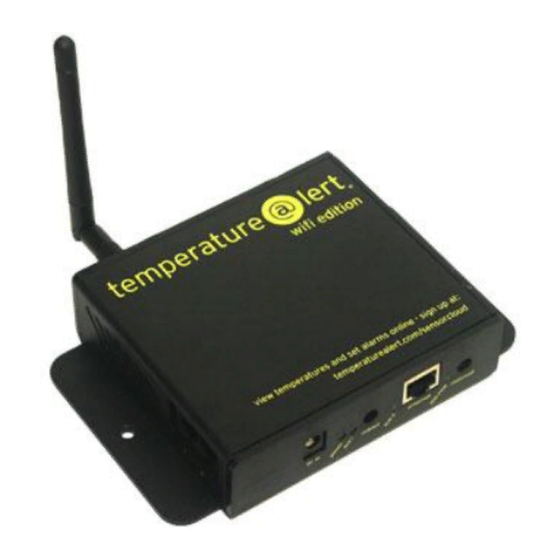
User Guide WiFi Edition at a Glance The Temperature@lert WiFi Edition measures the environmental conditions surrounding the sensor(s). If the sensor reading goes outside the specified threshold, the unit will alert you via email (Visit http://www.temperaturealert.com/sensorcloud to view our optional add-on service that provides Internet based monitoring for use with your WiFi Edition product). -
Page 9: Jacks And Connectors
Jacks and Connectors Figure 1 Sensor Jack 1 - Accepts any sensor made for the Temperature@lert WiFi Edition Model TM-WIFI220. Sensor Jack 2 - Accepts any sensor made for the Temperature@lert WiFi Edition Model TM-WIFI220. DC Power Jack - Temperature@lert WiFi Edition can be powered by connecting a 9-48V power supply (one is included with your device) to the DC Power Jack or via Ethernet (PoE) by using a power injector (sold separately). -
Page 10: Indicator Lights
0.10A / 4.8W 0.19A / 9.1W Reboot Button - Restarts the device when pressed and released. Pressing and holding the reboot button for 10 seconds will revert the unit back to factory default settings. Be sure to firmly press and hold the button, if the button “bounces”... -
Page 11: Connectivity Requirements
Aux 2 - Light used for custom applications at the operating system level. Can be programmed from the device's operating system. 100 Mbit – Indicates 100 Mbit Ethernet connection / activity. Connectivity Requirements In order to operate properly and send email alerts when the sensor readings fall outside your thresholds, the device requires Internet access via a wireless or wired Ethernet connection. -
Page 12: Default Ip Address
Default IP Address 10.99.99.1 Default Username and Password Username: admin Password: password You will see the current sensor reading along with a graph. This page will automatically refresh itself every few minutes. If you do not see a sensor reading or the reading is 0.00000, please see the Obtaining Service and Support section of this document. -
Page 13: Configuring The Device
Configuring the Device Status Page Figure 3 Navigation Figure three (3) shows the Status tab of the administrator interface; the other tabs used for configuration are displayed across the top. The Status tab displays the current sensor readings, while the Alarm Settings tab allows the 12 | Rev 2.1 for firmware 5.0+ | http://www.temperaturealert.com/ | ©... -
Page 14: The Graph
sensor thresholds to be set for each sensor and also allows the user to register the device with the optional Sensor Cloud service (http://www.temperaturealert.com/sensorcloud). The Connection Settings tab allows the wireless and wired network settings to be configured. The Mail Settings tab is used to specify what mail server to use for sending alarm notifications. -
Page 15: Xml Feed & Log File
XML Feed & Log File Figure 4 Figure four (4) above is an example of the XML feed data that can be viewed by clicking the ‘XML Log’ link at the top of the page. The Temperature and Error log files can be viewed by clicking their respective links. The XML feed can easily be integrated into other applications. -
Page 16: Logging In
Logging In If you click on any other tab, you will be prompted for a username/password. See Default Username and password earlier in this manual for the factory default. Alarm Settings Figure 5 15 | Rev 2.1 for firmware 5.0+ | http://www.temperaturealert.com/ | © 2011 Temperature@lert... -
Page 17: Connecting To Temperature@Lert Sensor Cloud
Figure five (5) shows the Alarm Settings tab which is used connect the device the optional sensor cloud service and set the thresholds for your sensors. You will also enter the email address of the recipient who will receive the alert emails. -
Page 18: Setting The Temperature Alarm
Figure 6 The first section in figure six (6) indicates if you are using the unit with Temperature@lert's optional Sensor Cloud service. Temperature@lert’s Sensor Cloud allows you to view temperatures and set alerts online from any browser-capable internet device. In addition, you can receive phone call notifications, configure alarm escalation, set ‘Missed Report’... -
Page 19: Connection Settings
If you connect new sensors or change which ports the sensors are connected to, you will need to press the ‘Reset Sensors’ button. Pressing the ‘Reset Sensors’ button will erase the data and alarms associated with the unit. The unit will automatically reboot after pressing ‘Reset Sensors’, detecting the new sensors. -
Page 20: Wireless Settings
Wireless Settings Figure 7 Figure seven (7) indicates the fields must be filled in order for your device to operate on your wireless network. One all the fields are complete click ‘Save Settings’ and the device will automatically reboot. After the device has restarted navigate to the ‘Connection Settings’... - Page 21 SSID – Enter your wireless network’s SSID (network name) or press the ‘Scan’ button to view available networks. If you do not know your SSID, please contact your IT technical support department. The SSID is CASE SENSITIVE. Encryption Type – Choose the type of encryption required for your wireless network.
- Page 22 Figure 8 Figure eight (8) indicated the fields that must be filled in if you want to give your device a static IP. Be sure click ‘Save Settings’ once all the fields have been entered. Temp@lert Device IP – The IP address on the wireless network to assign to your Temperature@lert WiFi unit.
-
Page 23: Ethernet Settings
NetMask – The net mask for the Temperature@lert WiFi unit’s wireless IP address. Gateway IP – The IP address of the gateway on your wireless network. DNS Server IP – The IP address of the DNS server on your wireless network. Ethernet Settings Figure 9 22 |... - Page 24 If you would like the device to automatically obtain an IP address from your wired Ethernet network, choose DHCP here. To specify a static IP address, choose ‘Static’ and fill in the fields shown in figure nine (9). NOTE: If you choose a static IP address, you must enter the IP, Net Mask, Gateway, and DNS fields in order to receive email alerts.
-
Page 25: Mail Settings
Mail Settings Figure 10 In order for the device to send email alerts, an SMTP server is required. Figure ten (10) indicates the required fields for the SMTP settings. The device requires an SMTP server that supports BASIC authentication. Contact your IT technical support department or email provider if you do not know your SMTP settings. - Page 26 SMTP Server – If you have a Gmail account select ‘Use Gmail SMTP server’ and enter your Gmail username and password. Otherwise, any SMTP server accessible from your network that supports BASIC authentication can be used. Accepts fully qualified domain names and IP addresses. Username –...
-
Page 27: Snmp Settings
SNMP Settings Figure eleven (11) indicates where the SNMP Trap settings are configured (the unit does not respond to SNMP Get requests at this time). If you do not know what SNMP is, you can ignore this section. Figure 11 SNMP Enabled –... - Page 28 SNMP Server IP – The IP address of where the SNMP Traps are to be sent. SNMP Server Port – The port of where the SNMP Traps are to be sent. SNMP Community – The Community String of your SNMP setup. 27 | Rev 2.1 for firmware 5.0+ | http://www.temperaturealert.com/ | ©...
-
Page 29: Preferences
Preferences Figure twelve (12) denotes the items you can customize in order to enable the device to fit your individual needs. Be sure to click ‘Save’ once you have entered all the settings. Figure 12 Device Nick Name – Provide the device with a nick name to be used on email alerts so you know which device the alert originates from. - Page 30 Units – Choose whether you want your temperature readings and alerts in degrees Fahrenheit or degrees Celsius. Reading Interval – Set the amount of time between sensor readings. The minimum is 1 minute. Enable Continuous Alert – Once the sensor falls outside your threshold, the device will send you an email alert.
-
Page 31: Help Page
Help Page Figure 13 Figure thirteen (13) shows the Help tab. The first item on this page indicates the current version of the firmware running on the unit. A link is provided to the Temperature@lert technical support site should you need to obtain technical support for this device. -
Page 32: Restoring Factory Defaults
network information’ link may be needed when experiencing trouble connecting to a wireless network. If you need to remotely reboot the device, use the reboot button. Finally, the license agreement for use of this device is presented. Restoring Factory Defaults To restore the unit to factory settings, visit http://www.temperaturealert.com/support and click on the Downloads... -
Page 33: Wireless Reception
day's temperature log file. This text file is then easily saved in your mailbox or to your PC's hard drive. Wireless Reception The unit requires a WiFi signal in order to operate wirelessly. The antenna should be oriented in a vertical position perpendicular to the horizon. -
Page 34: Specifications
Specifications WiFi220 Specification Sheet Model Temperature@lert WiFi Edition Part Number TM-WIFI220 Dimensions 1.25” x 4.00” x 6.00” (32 x 102 x 152 mm) Processor 32-bit MIPS R4Kc-class processor 183MHz Flash 64 Mbit (8MB) of 3V supply Flash memory 256Mbit (32MB) of 16-bit 166MHz SDRAM... - Page 35 Hardware Requirements Accessible WiFi Signal Internal Battery Back-Up Operation Internal Temperature Probe External Temperature Probe(s) Yes (1 or 2) Pre-Calibrated Sensor(s) Yes (1 or 2) Expansion Options 1 or 2 Sensors Standard (Up to 20 Special Order) Celsius and Fahrenheit User Selectable Real Time Temperature Alerts...
- Page 36 Embedded Software 6 ft. (1.8 m) External Temperature Sensor Included with Unit 110/240 VAC Adapter (North America Plug) Warranty 1 year Money Back Guarantee 30 Days Risk Free 35 | Rev 2.1 for firmware 5.0+ | http://www.temperaturealert.com/ | © 2011 Temperature@lert...
-
Page 37: Troubleshooting
Troubleshooting Unit Does Not Power On Check to make sure the unit is connected to wall power with the included power adapter or the unit is connected to a PoE connection with a power injector. PoE via powered hub or switch is not support. You must use a power injector if you choose to utilize PoE. -
Page 38: Check Dns And Gateway Settings
Check DNS and Gateway Settings In order to send email using the fully qualified domain name of your SMTP server, ensure that the DNS and Gateway fields on the SNMP settings page are set properly for the interface (wired or wireless) that is providing Internet access. -
Page 39: Check Sensor Connections
Check Sensor Connections Ensure there is at least one sensor connected to the sensor jacks on the side of the unit. The unit does not have any built in sensors. Remove and reseat the sensor from the jack and click the rescan button on the Alarm Settings page. Contact support if you are unable to view a temperature reading with a sensor cable connected. -
Page 40: Temperature Reading Is Wildly Inaccurate
1. The margin of error of the comparison tool. Many thermostats will have a much higher margin of error than the Temperature@lert WiFi Edition's sensor. 2. The temperature gradient of the room is in three dimensions. Measuring the temperature in one part of the room can yield a different result than in another part of the same room. -
Page 41: Obtaining Service And Support
Obtaining Service and Support We’ve worked very hard to ensure that the Temperature@lert WiFi Edition monitoring solution is simple and easy to use. Of course, we do realize that questions and other issues can pop up at any time. So, we’d love to hear from you.
Need help?
Do you have a question about the TM-WIFI220 and is the answer not in the manual?
Questions and answers