Table of Contents
Advertisement
Quick Links
AIR PRODUCTS
AIR PRODUCTS
AND
AND
CONTROLS
CONTROLS
You
You in Control
PRODUCT APPLICATION
SM-501 Series duct smoke detectors provide early detection of
smoke and products of combustion present in air moving through an
HVAC duct supply, return, or both in commercial, industrial, and res-
idential applications. These devices are designed to prevent the
recirculation of smoke in areas by the air handling system's fans,
and blowers. Complete systems may be shut down in the event of
smoke detection.
*
NOTE: For the correct installation of a duct smoke unit, please
refer to the NFPA 72 (National Fire Alarm Code), NFPA 90A
(Standard for Installation of Air Conditioning and Ventilation
Systems),NFPA 92A (Recommended Practice for Smoke Control
Systems.), NFPA 5000 (Building Construction and Safety Code),
IMC (International Mechanical Code), and IFC (International Fire
Code).
This detector is not intended for open area protection nor should it be used
for early warning detection or replace a regular fire detection system.
PRODUCT DESCRIPTION
The SM-501 Series smoke detector is fitted with a mounting base that
will accept an ionization smoke detector head model 55000-225APO
(or 55000-250APO) or photoelectric smoke detector head model
55000-328APO (or 55000-350APO). The duct unit supports two sets
of form "C" alarm contacts and one form "C" trouble contact. The trou-
ble contact supervises the presence of the input power and removal
of the detector head.
*
THE TROUBLE CONTACTS (TERMINALS 13-14-15) ARE
SHOWN IN THE NON-ENERGIZED CONDITION. IN NORMAL
OPERATION, CONTACTS WILL BE REVERSED.
The trouble contacts will not operate in the event of a smoke alarm.
The SM-501 Series duct detector will operate from various input
voltage sources; namely 24VAC, 24VDC, 115VAC and 230VAC.
SAMPLING TUBES
The operating principle of a duct detector is based on the Venturi
effect. Two tubes extend into the HVAC duct. Air flowing through the
duct is forced into the air intake (inlet) tube via the air intake holes,
(facing the airflow) and passes over the detector head. The air will be
drawn out via the exhaust tube back into the HVAC duct. (A 7"
exhaust tube is provided in the installation kit.) When the concentra-
tion of smoke particles suspended in the air stream reach the alarm
threshold of the detector head, the unit will go into alarm.
The duct smoke detector units are designed to operate in duct widths
from 6" to 10' wide with an air velocity between 500 to 4,000 feet per
minute. To verify correct installation, the pressure differential between
AIR PRODUCTS AND CONTROLS INC.
INSTALLATION AND MAINTENANCE INSTRUCTIONS
FOR SM-501 SERIES DUCT SMOKE DETECTORS
in Control
SM-501-N 4-Wire, Ionization Type
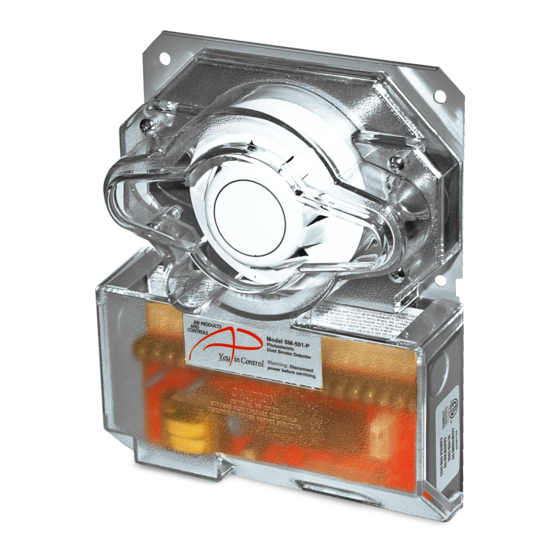
SM-501-P
PRODUCT OVERVIEW
4-Wire, Photoelectric Type
the sampling (high side) and exhaust (low side) tubes should be
measured using a Magnehelic pressure gauge or equivalent. An
acceptable reading is between 0.01 and 1.2 inches of water.
To minimize the impact of air turbulence and stratification on per-
formance, a duct smoke detector should be located as far as pos-
sible downstream from any obstruction (i.e. deflector plates, elbows,
dampers, etc.). In all situations, confirmation of velocity and pres-
sure differential within specifications is required.
REMOTE ACCESSORIES
Audible and visual alarm indicators, remote status indicators, and
remote reset/test switches can be accommodated by the SM-501
Series duct units by connecting to DC voltage output terminals 16
through 21. These terminals are not supervised and the
voltage/current will only be present when the detector unit is in
alarm. The remote pilot (green) LED will be permanently illuminat-
ed when connected to the output terminals as long as input power
and detector head are present.
SM-501 AT-A-GLANCE
MODEL NUMBER:
SM-501-N 4-Wire Ionization Duct Smoke Detector
SM-501-P 4-Wire Photoelectric Duct Smoke Detector
DETECTOR HEAD MODEL NUMBER:
Ionization Detector Head:
Photoelectric Detector Head: 55000-328APO
POWER REQUIREMENTS:
STANDBY CURRENT
24VAC
35.0mA
24VDC
15.0mA
115VAC 25.0mA
230VAC 12.0mA
RELAY CONTACT RATINGS:
Alarm contacts:
2 Sets form "C" rated at 10A @ 115VAC resistive
Trouble contacts:
1 Set form "C" rated at 10A @ 115VAC resistive
Air velocity:
500 to 4,000ft/min.
Ambient temperature: SM-501-N: 32°F to 158°F (0°C to 70°C)
SM-501-P: 32°F to 140°F (0°C to 60°C)
Humidity:
10% to 85% RH Non-Condensing/Non-Freezing
Material:
18GA steel back box, clear plastic cover
(Makrolon 94V-0)
Finish:
Gray paint on black box
Dimensions:
9 1/8" L X 7 1/4" W X 2 1/4" H
Max. net wt.:
3 1/2 lbs.
Radioactive element: SM-501-N (Ionization) - Americium 241,
0.9 micro curie.
Do not expose to corrosive atmospheres.
1
55000-225APO
ALARM CURRENT
24VAC
74.0mA
24VDC
56.0mA
115VAC 32.0mA
230VAC 16.0mA
INST APD0191 C081230
Advertisement
Table of Contents

Related Manuals for Air Products SM-501-N


Summary of Contents for Air Products SM-501-N
-
Page 1: Product Overview
500 to 4,000ft/min. effect. Two tubes extend into the HVAC duct. Air flowing through the Ambient temperature: SM-501-N: 32°F to 158°F (0°C to 70°C) duct is forced into the air intake (inlet) tube via the air intake holes, SM-501-P: 32°F to 140°F (0°C to 60°C) (facing the airflow) and passes over the detector head. -
Page 2: Mechanical Installation
NFPA and/or ICC docu- next longest standard size and cut down to the exact requirement. ments listed. Air Products and Controls assumes no responsibility for improperly installed duct detectors. To determine the correct... -
Page 3: Power Connections
ELECTRICAL INSTALLATION POWER CONNECTIONS Prior to connecting input power to the duct unit, determine the correct input voltage/ current availability and ensure it is connected to the correct terminals. 24VAC/VDC INPUTS 115VAC INPUT 230VAC INPUT Terminals 5, 6 Terminals 1,2,3. Terminals 1,2,4. - Page 4 FIRE ALARM CONTROL PANEL WIRING SAMPLE CONTROL PANEL WIRING - STYLE “D” / CLASS “A” IDC (Supervised - A fault condition will not inhibit an alarm response) UL Listed Conventional Fire Alarm Control Panel SM-501 Detector SM-501 Detector #X SAMPLE CONTROL PANEL WIRING - STYLE “B” / CLASS “B” IDC (Supervised - A fault condition will not inhibit an alarm response) UL Listed Conventional Fire Alarm...
-
Page 5: Testing Procedures
With the clear cover removed, air handling unit shut down, and using the head housing as this could contaminate the detector head and Air Products and Controls aerosol test smoke gas part number TG-1000, damage the casing. spray the test gas directly at the detector head from a distance of 12 inch- es for 2 seconds.
Need help?
Do you have a question about the SM-501-N and is the answer not in the manual?
Questions and answers