Table of Contents
Advertisement
Advertisement
Table of Contents

Subscribe to Our Youtube Channel
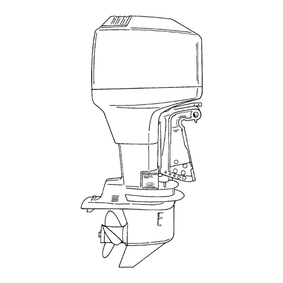
Summary of Contents for Mercury Two-stroke series
-
Page 1: Important Information
IMPORTANT INFORMATION OUTBOARD INSTALLATION... -
Page 2: Table Of Contents
Table of Contents Page Determining Recommended Outboard Mounting Height ......1D-1 Notice to Installer and Owner . -
Page 3: Notice To Installer And Owner
U.S. COAST GUARD CAPACITY have been specifically designed and tested for your outboard. MAXIMUM HORSEPOWER MAXIMUM PERSON Mercury Marine Quicksilver accessories are avail- CAPACITY (POUNDS) able from Mercury Marine dealers. MAXIMUM WEIGHT Some accessories not manufactured or sold by Mer-... -
Page 4: Determining Recommended Outboard Mounting Height
Determining Recommended WARNING Outboard Mounting Height Boat instability can occur at high speeds by installing engine at the wrong transom height. Contact the boat manufacturer for their recom- mendations for a specific engine installation. 26 in. (660m 25 in. (635m 24 in. -
Page 5: Locating Center Line Of The Outboard
NOTE: When drilling into a fiberglass boat, place Locating Center Line Of The masking tape directly onto boat where mounting Outboard holes will be drilled to help prevent fiberglass from chipping. Locate (and mark with pencil) the vertical centerline Use a 17/32 inch (13.5mm) diameter drill bit and drill (a) of boat transom. -
Page 6: Lifting Outboard
Lifting Outboard Installing Outboard To Boat Transom WARNING IMPORTANT: If boat is equipped with thru tilt tube Verify that the lifting ring is threaded into the fly- steering, steering cable end must be installed wheel a minimum of 5 turns and that hoist has a into tilt tube of outboard (port outboard only for maximum lift capacity over 500 lbs. -
Page 7: Single Steering Cable And Steering Link Rod Installation
Steering Link Rod Installation Single Steering Cable and Steering Link Rod IMPORTANT: The steering link rod that connects the steering cable to the engine must be fastened Installation using special washer head bolt (“a” – Part Num- ber 10-14000) and self locking nuts (“b”& “c”– NOTE: These instructions are for single cable–single Part Number 11-34863). -
Page 8: Co-Pilot Installation (Tiller Handle Models)
IMPORTANT: The co-pilot link rod (c) must be fas- Co-Pilot Installation (Tiller tened using self locking nylon insert locknuts Handle models) (“f”& “g”– Part Number 11-45592).These lock- nuts must never be replaced with common nuts WARNING (non locking) as they will work loose and vibrate off freeing the link rod to disengage. -
Page 9: Remote Control Installation
Remote Control Installation Shift and Throttle Cable Installation To The Outboard Refer to “Quicksilver Accessories Guide” to deter- mine correct length of remote control cables. Install the shift cable and throttle cable into the re- IMPORTANT: Remote control cables must be cor- mote control and mount the remote control following rect length. -
Page 10: Throttle Cable Installation
5. Place cable barrel into retainer and fasten the 3. Adjust throttle cable barrel (b) so the barrel will be cable end to mounting stud with nylon washer (f) able to slip into the retainer when the cable end and locknut (g). Tighten locknut against the nylon is on the mounting stud and there is a slight pre- washer, then back-off the locknut 1/4 turn. -
Page 11: Connecting Remote Wiring Harness
NOTE: The rubber grommet has to be lubricated to Connecting Remote Wiring ease installation. Harness To The Engine 1. Pull up the cowl seal (a) and remove the star- board side rubber grommet (b). 2. Take hold of the engine connector (c) and install the remote wiring harness plug (d). -
Page 12: Battery Connections
3. Push the connector and plug into the holder (e). Battery Connections CAUTION For dual outboard installations, the black (–) bat- tery cable of each engines starter motor ground circuit, MUST BE connected to each other by a common circuit (cable) capable of carrying the starting current of each engine’s starter motor. -
Page 13: Filling The Oil Injection System
Filling The Oil Injection System Bleeding Air From The Oil Injection System 1. Open the cowl cap (a). Turn the oil fill cap (b) to the left and remove. IMPORTANT: If air exists in either the oil pump in- let hose (a) or oil pump outlet hose (b), the air MUST BE bled from the hose(s) or engine dam- age may occur. -
Page 14: Adjusting The Oil Injection Pump
Adjusting The Oil Injection Pump Trim Tab Adjustment When carburetor linkage is at idle position, alignment Propeller steering torque will cause your boat to pull mark (a) on oil injection arm should be in-line with in one direction. This steering torque is a normal thing mark (b) on pump as shown.


Need help?
Do you have a question about the Two-stroke series and is the answer not in the manual?
Questions and answers