Table of Contents
Advertisement
Advertisement
Table of Contents

Subscribe to Our Youtube Channel
Related Manuals for Mazi INVR-16A

Summary of Contents for Mazi INVR-16A
- Page 1 INVR-16A / INVR-32A Network Video Recorder User Manual v1.0...
- Page 2 User Manual of MAZi INVR-16A/32A Regulatory information FCC information compliance: This equipment has been tested and found to comply with the limits for a digital device, pursuant to part 15 of the FCC Rules. These limits are designed to provide reasonable protection against harmful interference when the equipment is operated in a commercial environment.
- Page 3 User Manual of MAZi INVR-16A/32A Preventive and Cautionary Tips Before connecting and operating your device, please be advised of the following tips: Ensure unit is installed in a well-ventilated, dust-free environment. Unit is designed for indoor use only. Keep all liquids away from the device.
-
Page 4: Product Key Features
User Manual of MAZi INVR-16A/32A Product Key Features General Connectable to network cameras, network dome and encoders. Connectable to the third-party network cameras like ACTI, Arecont, AXIS, Bosch, Brickcom, Canon, PANASONIC, Pelco, SAMSUNG, SANYO, SONY, Vivotek and ZAVIO, and cameras that adopt ONVIF or PSIA protocol. - Page 5 User Manual of MAZi INVR-16A/32A Reverse playback of multi-channel. Supports pause, play reverse, speed up, speed down, skip forward, and skip backward when playback, and locating by dragging the mouse. Up to 16-ch synchronous playback at 4CIF real time. Manual capture, continuous capture of video images and playback of captured pictures.
- Page 6 User Manual of MAZi INVR-16A/32A Remote PTZ control. Remote JPEG capture. Two-way audio and voice broadcasting. Embedded WEB server. Development Scalability: SDK for Windows and Linux system. Source code of application software for demo. Development support and training for application system.
-
Page 7: Table Of Contents
User Manual of MAZi INVR-16A/32A TABLE OF CONTENTS ....................Chapter 1 Introduction 11 1.1 Front Panel ............................12 1.2 IR Remote Control Operations ......................14 1.3 USB Mouse Operation ........................16 1.4 Input Method Description........................ 17 1.5 Menu Operation..........................18 1.6 Rear Panel ............................ - Page 8 User Manual of MAZi INVR-16A/32A 5.8 Configuring HDD Group for Recording and Capture..............66 5.9 Files Protection..........................67 Chapter 6 Playback ............................69 6.1 Playing Back Record Files ......................70 6.1.1 Playing Back by Channel .................... 70 6.1.2 Playing Back by Time ....................72 6.1.3...
- Page 9 User Manual of MAZi INVR-16A/32A 9.2.11 Configuring NAT (UPnP™)..................133 9.2.12 Configuring High-speed Download ................135 9.3 Checking Network Traffic ......................136 9.4 Configuring Network Detection ....................137 9.4.1 Testing Network Delay and Packet Loss..............137 9.4.2 Exporting Network Packet ..................137 9.4.3...
- Page 10 User Manual of MAZi INVR-16A/32A 13.5.2 Deleting a User ......................178 13.5.3 Editing a User ......................179 Appendix ..............................181 Glossary ..............................182 Troubleshooting ............................. 183 List of Compatible IP Cameras ......................189...
-
Page 11: Chapter 1
User Manual of MAZi INVR-16A/32A Chapter 1 Introduction... -
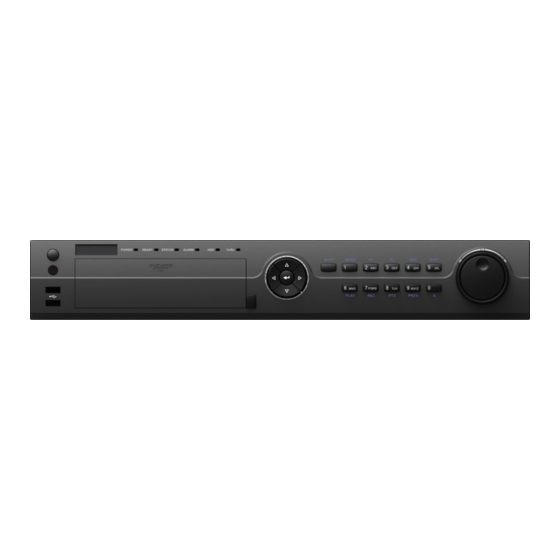
Page 12: Front Panel
User Manual of MAZi INVR-16A/32A 1.1 Front Panel Figure 1. 1 INVR-16A/32A Table 1. 1 Description of Control Panel Buttons Name Function Description POWER Turns green when NVR is powered up. READY The indicator is green when the device is running normally. - Page 13 User Manual of MAZi INVR-16A/32A Name Function Description Enter letters “ABC”; The F1 button when used in a list field will select all items in the list. In PTZ Control mode, it will turn on/off PTZ light and when the image is zoomed in, the key is used to zoom out.
-
Page 14: Ir Remote Control Operations
User Manual of MAZi INVR-16A/32A 1.2 IR Remote Control Operations The NVR may also be controlled with the included IR remote control, shown in Figure 1. 2. Batteries (2×AAA) must be installed before operation. Figure 1. 2 Remote Control The keys on the remote control closely resemble the ones on the front panel. See Table 1. 2. - Page 15 User Manual of MAZi INVR-16A/32A Name Description PREV Button Same as the PREV/FOCUS- button on front panel. Same as the DIRECTION/ENTER buttons on front panel. DIRECTION/ENTER Buttons Same as the PTZ/IRIS- button on front panel. PTZ Button ESC Button Same as the ESC button on front panel.
-
Page 16: Usb Mouse Operation
User Manual of MAZi INVR-16A/32A 1.3 USB Mouse Operation A regular 3-button (Left/Right/Scroll-wheel) USB mouse can also be used with this NVR. To use a USB mouse: 1. Plug USB mouse into one of the USB interfaces on the front panel of the NVR. -
Page 17: Input Method Description
User Manual of MAZi INVR-16A/32A 1.4 Input Method Description Figure 1. 3 Soft Keyboard Description of the buttons on the soft keyboard: Table 1. 4 Description of the Soft Keyboard Icons Icons Description Icons Description Lowercase/Uppercase Symbols Space Backspace Exit... -
Page 18: Menu Operation
User Manual of MAZi INVR-16A/32A 1.5 Menu Operation After entering the menu, the menu bar on the top of the screen can be clicked to set other functions. Figure 1. 4 Menu Bar From the left to the right, each icon stands for Playback, Export, Manual, HDD, Record, Camera, Configuration,... -
Page 19: Rear Panel
User Manual of MAZi INVR-16A/32A 1.6 Rear Panel Figure 1. 5 INVR-16A/32A Table 1. 5 Description of Rear Panel Interfaces Item Description VIDEO OUT BNC connector for video output. BNC connector for audio output. This connector is synchronized with CVBS AUDIO OUT CVBS video output. -
Page 20: Chapter 2 Getting Started
User Manual of MAZi INVR-16A/32A Chapter 2 Getting Started... -
Page 21: Starting Up And Shutting Down The Nvr
User Manual of MAZi INVR-16A/32A 2.1 Starting Up and Shutting Down the NVR Purpose: Proper startup and shutdown procedures are crucial to expanding the life of the NVR. Before you start: Check that the voltage of the extra power supply is the same with the NVR’s requirement, and the ground connection is working properly. - Page 22 User Manual of MAZi INVR-16A/32A 2. Enter the administrator’s username and password in the dialog box for authentication. 3. Click the Yes button. Do not press the POWER button again when the system is shutting down. Rebooting the NVR In the Shutdown menu, you can also reboot the NVR.
-
Page 23: Using The Wizard For Basic Configuration
User Manual of MAZi INVR-16A/32A 2.2 Using the Wizard for basic configuration By default, the Setup Wizard starts once the NVR has loaded, as shown in Figure 2. 4. Select the system language in the drop-down list, and click the Apply button to save the setting. - Page 24 User Manual of MAZi INVR-16A/32A Figure 2. 5 Login Window 3. Enter the admin password. By default, the password is 12345. 4. To change the admin password, check the New Admin Password checkbox. Enter the new password and confirm the password in the given fields.
- Page 25 User Manual of MAZi INVR-16A/32A 7. Click Next button after you configured the network parameters, which takes you to the HDD Management window, shown in Figure 2. 8. Figure 2. 8 HDD Management 8. To initialize the HDD, click the Init button. Initialization removes all the data saved in the HDD.
- Page 26 User Manual of MAZi INVR-16A/32A 12. Click Copy to copy the settings to other channels, as shown in Figure 2. 11. Figure 2. 11 Copy Record Settings 13. Click OK to complete the startup Setup Wizard.
-
Page 27: Adding And Connecting The Ip Cameras
User Manual of MAZi INVR-16A/32A 2.3 Adding and Connecting the IP Cameras 2.3.1 Adding the Online IP Cameras Purpose: The main function of the NVR is to connect the network cameras and record the video got from it. So before you can get a live view or record of the video, you should add the network cameras to the connection list of the device. - Page 28 User Manual of MAZi INVR-16A/32A Explanation of the icons: Icon Explanation Icon Explanation Edit basic parameters of the camera Add the detected IP camera. The camera is connected; you can The camera is disconnected; you can click the icon to get the live view of click the icon to get the exception the camera.
-
Page 29: Editing The Connected Ip Cameras And Configuring Customized Protocols
User Manual of MAZi INVR-16A/32A Repeat the step 1 and 2 of adding IP cameras manually to add the camera. Figure 2. 16 IP Camera Management Interface 2.3.2 Editing the Connected IP cameras and Configuring Customized Protocols After the adding of the IP cameras, the basic information of the camera lists in the page, you can configure the basic setting of the IP cameras. - Page 30 User Manual of MAZi INVR-16A/32A Drag the horizontal scroll bar to the right side and click the icon. Figure 2. 18 Network Configuration of the Camera You can edit the network information and the password of the camera. Figure 2. 19 Password Configuration of the Camera Click Apply to save the settings and click OK to exit the interface.
- Page 31 User Manual of MAZi INVR-16A/32A Figure 2. 20 Protocol Management Interface There are 16 customized protocols provided in the system, you can edit the protocol name; and choose whether to enable the sub-stream. Choose the protocol type of transmission and choose the transfer protocols.
-
Page 32: Chapter 3 Live View
User Manual of MAZi INVR-16A/32A Chapter 3 Live View... -
Page 33: Introduction Of Live View
User Manual of MAZi INVR-16A/32A 3.1 Introduction of Live View Live view shows you the video image getting from each camera in real time. The NVR automatically enters Live View mode when powered on. It is also at the very top of the menu hierarchy, thus pressing the ESC many times (depending on which menu you’re on) brings you to the Live View mode. -
Page 34: Operations In Live View Mode
User Manual of MAZi INVR-16A/32A 3.2 Operations in Live View Mode In live view mode, there are many functions provided. The functions are listed below. • Single Screen: showing only one screen on the monitor. • Multi-screen: showing multiple screens on the monitor simultaneously. -
Page 35: Using The Mouse In Live View
User Manual of MAZi INVR-16A/32A 3.2.2 Using the Mouse in Live View Table 3. 4 Mouse Operation in Live View Name Description Enter the menu of the system by clicking the icon. Switch to the single full screen. Adjust the screen layout by clicking the specific icon. -
Page 36: Using An Auxiliary Monitor
User Manual of MAZi INVR-16A/32A 3.2.3 Using an Auxiliary Monitor Certain features of the Live View are also available while in an Aux monitor. These features include: • Single Screen: Switch to a full screen display of the selected camera. Camera can be selected from a dropdown list. - Page 37 User Manual of MAZi INVR-16A/32A Figure 3. 3 Digital Zoom Image Settings icon can be selected to enter the Image Settings menu. You can set the image parameters like brightness, contrast, saturation and hue. Figure 3. 4 Image Settings- Preset Live View Strategy can be selected to set strategy, including Real-time, Balanced, Fluency.
-
Page 38: Adjusting Live View Settings
User Manual of MAZi INVR-16A/32A 3.3 Adjusting Live View Settings Purpose: Live View settings can be customized according to different needs. You can configure the output interface, dwell time for screen to be shown, mute or turning on the audio, the screen number for each channel, etc. - Page 39 User Manual of MAZi INVR-16A/32A To set the camera order: 1) Select a View mode in 2) Select the small window, and double-click on the channel number to display the channel on the window. You can click button to start live view for all the channels and click to stop all the live view.
-
Page 40: Channel-Zero Encoding
User Manual of MAZi INVR-16A/32A 3.4 Channel-zero Encoding Purpose: Sometimes you need to get a remote view of many channels in real time from web browser or CMS(Client Management System) software, in order to decrease the bandwidth requirement without affecting the image quality, channel-zero encoding is supported as an option for you. -
Page 41: User Logout
User Manual of MAZi INVR-16A/32A 3.5 User Logout Purpose: After logging out, the monitor turns to the live view mode and if you want to do some operation, you need to enter user name and password tog in again. Steps: 1. -
Page 42: Chapter 4 Ptz Controls
User Manual of MAZi INVR-16A/32A Chapter 4 PTZ Controls... -
Page 43: Configuring Ptz Settings
User Manual of MAZi INVR-16A/32A 4.1 Configuring PTZ Settings Purpose: Follow the procedure to set the parameters for PTZ. The configuring of the PTZ parameters should be done before you control the PTZ camera. Steps: 1. Enter the PTZ Settings interface. -
Page 44: Setting Ptz Presets, Patrols & Patterns
User Manual of MAZi INVR-16A/32A 4.2 Setting PTZ Presets, Patrols & Patterns Before you start: Please make sure that the presets, patrols and patterns should be supported by PTZ protocols. 4.2.1 Customizing Presets Purpose: Follow the steps to set the Preset location which you want the PTZ camera to point to when an event takes place. -
Page 45: Calling Presets
User Manual of MAZi INVR-16A/32A 4.2.2 Calling Presets Purpose: This feature enables the camera to point to a specified position such as a window when an event takes place. Call preset in the PTZ setting interface: Steps: 1. Enter the PTZ Control interface. -
Page 46: Customizing Patrols
User Manual of MAZi INVR-16A/32A 4.2.3 Customizing Patrols Purpose: Patrols can be set to move the PTZ to different key points and have it stay there for a set duration before moving on to the next key point. The key points are corresponding to the presets. The presets can be set following the steps above in Customizing Presets. -
Page 47: Calling Patrols
User Manual of MAZi INVR-16A/32A Repeat the above steps to add more key points. Click the icon to delete the corresponding key point, and click the trash icon to delete all the key points. Select a key point, then click button to adjust the order of the key points. -
Page 48: Customizing Patterns
User Manual of MAZi INVR-16A/32A Figure 4. 9 PTZ Panel - Patrol 4.2.5 Customizing Patterns Purpose: Patterns can be set by recording the movement of the PTZ. You can call the pattern to make the PTZ movement according to the predefined path. -
Page 49: Calling Patterns
User Manual of MAZi INVR-16A/32A 4.2.6 Calling Patterns Purpose: Follow the procedure to move the PTZ camera according to the predefined patterns. Calling pattern in the PTZ setting interface Steps: 1. Enter the PTZ Control interface. Menu>Camera>PTZ>More Settings 2. Select the pattern number. -
Page 50: Ptz Control Panel
User Manual of MAZi INVR-16A/32A 4.3 PTZ Control Panel In the Live View mode, you can press the PTZ Control button on the front panel or on the remote control, or choose the PTZ Control icon to enter the PTZ panel. -
Page 51: Chapter 5 Record And Capture Settings
User Manual of MAZi INVR-16A/32A Chapter 5 Record and Capture Settings... -
Page 52: Configuring Parameters
User Manual of MAZi INVR-16A/32A 5.1 Configuring Parameters Purpose: By configuring the encoding parameters you can define the parameters which affect the image quality, such as the transmission stream type, the resolution and so on. Before you start: 1. Make sure that the HDD has already been installed. If not, please install a HDD and initialize it. - Page 53 User Manual of MAZi INVR-16A/32A Select Record tab page to configure. You can configure the stream type (Normal and Event), the resolution, and other parameters on your demand. • Pre-record: The time you set to record before the scheduled time or event. For example, when an alarm triggered the recording at 10:00, if you set the pre-record time as 5 seconds, the camera records it at 9:59:55.
- Page 54 User Manual of MAZi INVR-16A/32A Configure the parameters. Click Apply to save the settings. The interval is the time period between two capturing actions. You can configure all the parameters on this menu on your demand.
-
Page 55: Configuring Record/Capture Schedule
User Manual of MAZi INVR-16A/32A 5.2 Configuring Record/Capture Schedule Purpose: Set the record schedule, and then the camera automatically starts/stops recording according to the configured schedule. In this chapter, we take the record schedule procedure as an example, and the same procedure can be applied to configure schedule for both recording and capture. - Page 56 User Manual of MAZi INVR-16A/32A Figure 5. 7 Recording Schedule Interface You can click the button to set the accurate time of the schedule. To schedule an all-day recording, check the checkbox after the All Day item. Figure 5. 8 Edit Schedule III.
- Page 57 User Manual of MAZi INVR-16A/32A Draw the schedule: Click on the color icons, you can choose the schedule type as continuous or event. Figure 5. 10 Draw the Schedule Descriptions of the color icons are shown in the figure below.
-
Page 58: Configuring Motion Detection Record And Capture
User Manual of MAZi INVR-16A/32A 5.3 Configuring Motion Detection Record and Capture Purpose: Follow the steps to set the motion detection parameters. In the live view mode, once a motion detection event takes place, the NVR can analyze it and do many actions to handle it. Enabling motion detection function can trigger certain channels to start recording, or trigger full screen monitoring, audio warning, notify the surveillance center and so on. - Page 59 User Manual of MAZi INVR-16A/32A 4) Click Settings, and the message box for channel information pop up. Figure 5. 15 Motion Detection Handling 5) Select the channels which you want the motion detection event to trigger recording. 6) Click Apply to save the settings.
-
Page 60: Configuring Alarm Triggered Record And Capture
User Manual of MAZi INVR-16A/32A 5.4 Configuring Alarm Triggered Record and Capture Purpose: Follow the procedure to configure alarm triggered recording or capture. Steps: Enter the Alarm setting interface. Menu> Configuration> Alarm Figure 5. 16 Alarm Settings Click Alarm Input. - Page 61 User Manual of MAZi INVR-16A/32A Figure 5. 18 Alarm Settings 5) Choose the alarm triggered recording channel. 6) Check the checkbox to select channel. 7) Click Apply to save settings. 8) Click OK to back to the upper level menu.
-
Page 62: Manual Record And Continuous Capture
User Manual of MAZi INVR-16A/32A 5.5 Manual Record and Continuous Capture Purpose: Follow the steps to set parameters for the manual record and continuous capture. Using manual record and continuous capture, you need to manually cancel the record and capture. The manual recording and manual continuous capture is prior to the scheduled recording and capture. -
Page 63: Configuring Holiday Record And Capture
User Manual of MAZi INVR-16A/32A 5.6 Configuring Holiday Record and Capture Purpose: Follow the steps to configure the record or capture schedule on holiday for that year. You may want to have different plan for recording and capture on holiday. -
Page 64: Configuring Redundant Recording And Capture
User Manual of MAZi INVR-16A/32A 5.7 Configuring Redundant Recording and Capture Purpose: Enabling redundant recording and capture, which means saving the record files and captured pictures not only in the R/W HDD but also in the redundant HDD, will effectively enhance the data safety and reliability. . - Page 65 User Manual of MAZi INVR-16A/32A Figure 5. 26 Record Parameters Select Camera you want to configure in the drop-down list. Check the checkbox of Redundant Record/Capture. Click OK to save settings and back to the upper level menu. Repeat the above steps for configuring other channels.
-
Page 66: Configuring Hdd Group For Recording And Capture
User Manual of MAZi INVR-16A/32A 5.8 Configuring HDD Group for Recording and Capture Purpose: You can group the HDDs and save the record files and captured pictures in certain HDD group. Steps: Enter HDD setting interface. Menu>HDD Figure 5. 27 HDD General Select Advanced on the left bar. -
Page 67: Files Protection
User Manual of MAZi INVR-16A/32A 5.9 Files Protection Purpose: You can lock the recorded files or set the HDD property to Read-only to protect the record files from being overwritten. Protect file by locking the record files: Steps: Enter Export setting interface. - Page 68 User Manual of MAZi INVR-16A/32A Figure 5. 31 Unlocking Attention Protect file by setting HDD property to Read-only Steps: Enter HDD setting interface. Menu> HDD Figure 5. 32 HDD General Click to edit the HDD you want to protect. To edit HDD property, you need to set the storage mode of the HDD to Group. See Chapter Managing HDD Group.
-
Page 69: Chapter 6 Playback
User Manual of MAZi INVR-16A/32A Chapter 6 Playback... -
Page 70: Playing Back Record Files
User Manual of MAZi INVR-16A/32A 6.1 Playing Back Record Files 6.1.1 Playing Back by Channel Purpose: Playback the recorded video files of a specific channel in the live view mode. Channel switch is supported. OPTION 1: Choose a channel in live view mode using the mouse and click the button in the quick setting toolbar. - Page 71 User Manual of MAZi INVR-16A/32A The toolbar in the bottom part of Playback interface can be used to control playing progress, as shown in Figure 6. 3. Figure 6. 3 Playback Interface Click the channel(s) to execute simultaneous playback of multiple channels.
-
Page 72: Playing Back By Time
User Manual of MAZi INVR-16A/32A Playback progress bar: use the mouse to click any point of the progress bar or drag the progress bar to locate special frames. 6.1.2 Playing Back by Time Purpose: Play back video files recorded in specified time duration. Multi-channel simultaneous playback and channel switch are supported. - Page 73 User Manual of MAZi INVR-16A/32A Figure 6. 6 Interface of Playback by Time Figure 6. 7 Toolbar of Playback by Time indicates the start/end time of the record. Table 6. 2 Detailed Explanation of Playback-by-time Interface Button Operation Button Operation...
-
Page 74: Playing Back By Event Search
User Manual of MAZi INVR-16A/32A Playback progress bar: use the mouse to click any point of the progress bar or drag the progress bar to locate special frames. 6.1.3 Playing Back by Event Search Purpose: Play back record files on one or several channels searched out by restricting event type (e.g. alarm input and motion detection). - Page 75 User Manual of MAZi INVR-16A/32A Figure 6. 9 Motion Search Interface 4. Click Search button to get the search result information. You may refer to the right-side bar for the result. Figure 6. 10 Search Result Bar(Alarm In and Motion) 5.
- Page 76 User Manual of MAZi INVR-16A/32A The toolbar in the bottom part of Playback interface can be used to control playing process. Figure 6. 11 Interface of Playback by Event Figure 6. 12 Toolbar of Playback by Event Table 6. 3 Detailed Explanation of Playback-by-event Toolbar...
-
Page 77: Playing Back By Tag
User Manual of MAZi INVR-16A/32A 6.1.4 Playing Back by Tag Purpose: Video tag allows you to record related information like people and location of a certain time point during playback. You are also allowed to use video tag(s) to search for record files and position time point. - Page 78 User Manual of MAZi INVR-16A/32A Figure 6. 14 Tag Management Interface Steps: 1. Select the Tag from the drop-down list in the Playback interface. 2. Choose channels, edit start time and end time, and then click Search to enter Search Result interface.
- Page 79 User Manual of MAZi INVR-16A/32A Figure 6. 16 Interface of Playback by Tag Figure 6. 17 Toolbar of Playback by Tag Table 6. 4 Detailed Explanation of Playback-by-tag Toolbar Button Operation Button Operation Button Operation Button Operation Audio on/ Start/Stop...
-
Page 80: Playing Back By System Logs
User Manual of MAZi INVR-16A/32A 6.1.5 Playing Back by System Logs Purpose: Play back record file(s) associated with channels after searching system logs. Steps: 1. Enter Log Information interface. Menu>Maintenance>Log Information 2. Click Log Search tab to enter Playback by System Logs. -
Page 81: Playing Back External File
User Manual of MAZi INVR-16A/32A Figure 6. 19 Result of System Log Search 4. Playback interface. The toolbar in the bottom part of Playback interface can be used to control playing process. Figure 6. 20 Interface of Playback by Log 6.1.6 Playing Back External File... - Page 82 User Manual of MAZi INVR-16A/32A Figure 6. 21 Interface of External File Playback...
-
Page 83: Auxiliary Functions Of Playback
User Manual of MAZi INVR-16A/32A 6.2 Auxiliary Functions of Playback 6.2.1 Playing Back Frame by Frame Purpose: Play video files frame by frame, in case of checking image details of the video when abnormal events happen. Steps: • Using a Mouse: Go to Playback interface. - Page 84 User Manual of MAZi INVR-16A/32A Figure 6. 22 Interface of Playback by Time 2. Click the on the playback control toolbar to enter Smart Search mode. 3. Click and drag the mouse to draw area(s). You can click button to set the full screen as target searching area.
- Page 85 User Manual of MAZi INVR-16A/32A Figure 6. 24 Smart Search Result Figure 6. 25 Toolbar of Smart Search Playback indicates the start/end time of the record. Table 6. 5 Detailed Explanation of Smart-search-playback Toolbar Button Operation Button Operation Button Operation...
-
Page 86: Digital Zoom
User Manual of MAZi INVR-16A/32A 6.2.3 Digital Zoom Steps: 1. Click the button on the playback control bar to enter Digital Zoom interface. 2. Use the mouse to draw a red rectangle and the image within it will be enlarged up to 16 times. - Page 87 User Manual of MAZi INVR-16A/32A Figure 6. 27 4-ch Synchronous Playback Interface 3. Click to play back the record files reversely.
-
Page 88: Picture Playback
User Manual of MAZi INVR-16A/32A 6.3 Picture Playback Purpose: Search and view captured pictures stored in HDD. Steps: 1. Enter Playback interface. Menu>Playback 2. Select the Picture in the drop-down list on the top-left side. Figure 6. 28 Interface of Playback by Picture 3. - Page 89 User Manual of MAZi INVR-16A/32A 5. The toolbar in the bottom part of Playback interface can be used to control playing process. Figure 6. 30 Picture Playback Toolbar Table 6. 6 Detailed Explanation of Picture-playback Toolbar ikonok Button Function Button...
-
Page 90: Chapter 7 Backup
User Manual of MAZi INVR-16A/32A Chapter 7 Backup... -
Page 91: Backing Up Record Files
User Manual of MAZi INVR-16A/32A 7.1 Backing up Record Files 7.1.1 Backing up by Normal Video Search Purpose: The record files can be backup to various devices, such as USB devices (USB flash drives, USB HDDs, USB writer), SATA writer and e-SATA HDD. - Page 92 User Manual of MAZi INVR-16A/32A 4. Click Export button and start backup. If the inserted USB device is not recognized: • Click the Refresh button. • Reconnect device. • Check for compatibility from vendor. You can also format USB flash drives or USB HDDs via the device.
- Page 93 User Manual of MAZi INVR-16A/32A Figure 7. 5 Export Finished 6. Check backup result. Choose the record file in Export interface and click button to check it. Backup using USB writer and SATA writer Steps: 1. Enter Export interface. Menu>Export>Normal 2.
- Page 94 User Manual of MAZi INVR-16A/32A Figure 7. 7 Result of Normal Video Search for Backup 4. Export. Click Export button and start backup. If the inserted USB writer or SATA writer is not recognized: • Click the Refresh button. •...
- Page 95 User Manual of MAZi INVR-16A/32A Figure 7. 9 Export Options Stay in the Exporting interface until all record files are exported with pop-up message box “Export finished”. Figure 7. 10 Export Finished 6. Check backup result. Choose the record file in Export interface and click button to check it.
- Page 96 User Manual of MAZi INVR-16A/32A Figure 7. 11 Normal Video Search for Backup 3. Select record files you want to back up. Click button to play the record file if you want to check it. Tick record files you want to back up.
-
Page 97: Backing Up By Event Search
User Manual of MAZi INVR-16A/32A Figure 7. 13 Export by Normal Video Search Using eSATA HDD 5. Select the file type in the by clicking the icon of corresponding option and click the OK button to start backup. Figure 7. 14 Export Options Stay in the Exporting interface until all record files are exported with pop-up message box “Export finished”. - Page 98 User Manual of MAZi INVR-16A/32A Steps: 1. Enter Export interface. Menu>Export>Event 1) Select “Motion” from the dropdown list of Event Type. Event types contain Alarm Input and Motion, here we take the backing up by motion as an example. 2) Select the alarm input No. and time.
- Page 99 User Manual of MAZi INVR-16A/32A Figure 7. 18 Event Details Interface 3. Click the Export button and start back up. If the inserted USB device is not recognized: • Click the Refresh button. • Reconnect device. • Check for compatibility from vendor.
-
Page 100: Backing Up Video Clips
User Manual of MAZi INVR-16A/32A Figure 7. 20 Export Options Stay in the Exporting interface until all record files are exported with pop-up message box “Export finished”. Figure 7. 21 Export Finished 5. Choose the record file in Export interface and click button to check it. - Page 101 User Manual of MAZi INVR-16A/32A Figure 7. 22 Interface of Playback by Time 4. Click Yes to save video clips and enter Export interface, or click No to quit and do not save video clips. Figure 7. 23 Attention to Video Clip Saving If the inserted USB device is not recognized: •...
- Page 102 User Manual of MAZi INVR-16A/32A Figure 7. 24 Export Video Clips Using USB Flash Drive 5. Select the file type in the by clicking the icon of corresponding option and click the OK button to start backup. Figure 7. 25 Export Options Stay in the Exporting interface until all record files are exported with pop-up message “Export finished”.
-
Page 103: Backing Up Pictures
User Manual of MAZi INVR-16A/32A 7.2 Backing up Pictures Purpose: Back up pictures using USB devices (USB flash drives, USB HDDs, USB writer), SATA writer or eSATA HDD. Steps: 1. Enter Export interface. Menu>Export>Picture Select channel(s), image type, start time and end time, and click Search button to enter the Search Result interface. - Page 104 User Manual of MAZi INVR-16A/32A 3. Click Export button and start backup. Figure 7. 29 Export Pictures Using USB Flash Drive Stay in the Exporting interface until all record files are exported with pop-up message “Export finished”. Figure 7. 30 Export Finished...
-
Page 105: Managing Backup Devices
User Manual of MAZi INVR-16A/32A 7.3 Managing Backup Devices Management of USB flash drives, USB HDDs and eSATA HDDs. Enter Search Result interface of record files. Menu>Export>Normal Set search condition and click Search button to enter Search Result interface. At least one camera shall be selected. - Page 106 User Manual of MAZi INVR-16A/32A Click Format button to format the backup device. If the inserted USB device is not recognized: • Click the Refresh button. • Reconnect device. • Check for compatibility from vendor. Figure 7. 33 USB Flash Drive Management Management of USB writers and DVD-R/W Enter Search Result interface of record files.
- Page 107 User Manual of MAZi INVR-16A/32A Figure 7. 35 Result of Normal Video Search for Backup Backup device management. Click Erase button if you want to erase the files from a re-writable CD/DVD. There must be a re-writable CD/DVD when you make this operation.
-
Page 108: Chapter 8 Alarm Settings
User Manual of MAZi INVR-16A/32A Chapter 8 Alarm Settings... -
Page 109: Setting Motion Detection Alarm
User Manual of MAZi INVR-16A/32A 8.1 Setting Motion Detection Alarm Steps: 1. Enter Motion Detection interface of Camera Management and choose a camera you want to set up motion detection. Menu> Camera> Motion Figure 8. 1 Motion Detection Setup Interface 2. - Page 110 User Manual of MAZi INVR-16A/32A Time periods shall not be repeated or overlapped. Figure 8. 3 Set Arming Schedule of Motion Detection 5. Click Handling tab to set up alarm response actions of motion alarm (please refer to Chapter Setting Alarm Response Actions).
-
Page 111: Setting Sensor Alarms
User Manual of MAZi INVR-16A/32A 8.2 Setting Sensor Alarms Purpose: Set the handling action of an external sensor alarm. Steps: 1. Enter Alarm Settings of System Configuration and select an alarm input. Menu> Configuration> Alarm Select Alarm Input tab to enter Alarm Input Settings interface. - Page 112 User Manual of MAZi INVR-16A/32A Figure 8. 6 Set Arming Schedule of Alarm Input Choose one day of a week and Max. eight time periods can be set within each day, and click Apply to save the settings. Time periods shall not be repeated or overlapped.
- Page 113 User Manual of MAZi INVR-16A/32A Figure 8. 8 Copy Settings of Alarm Input...
-
Page 114: Detecting Video Loss Alarm
User Manual of MAZi INVR-16A/32A 8.3 Detecting Video Loss Alarm Purpose: Detect video loss of a channel and take alarm response action(s). Steps: 1. Enter Video Loss interface of Camera Management and select a channel you want to detect. Menu> Camera> Video Loss Figure 8. - Page 115 User Manual of MAZi INVR-16A/32A Figure 8. 10 Set Arming Schedule of Video Loss 4. Select Linkage Action tab to set up alarm response action of video loss (please refer to Chapter Setting Alarm Response Actions). 5. Click the OK button to complete the video loss settings of the channel.
-
Page 116: Detecting Video Tampering Alarm
User Manual of MAZi INVR-16A/32A 8.4 Detecting Video Tampering Alarm Purpose: Trigger alarm when the lens is covered and take alarm response action(s). Steps: 1. Enter Video Tampering interface of Camera Management and select a channel you want to detect video tampering. - Page 117 User Manual of MAZi INVR-16A/32A Time periods shall not be repeated or overlapped. Figure 8. 13 Set Arming Schedule of Video Tampering 4. Select Linkage Action tab to set up alarm response actions of video tampering alarm (please refer to Chapter Setting Alarm Response Actions).
-
Page 118: Handling Exceptions Alarm
User Manual of MAZi INVR-16A/32A 8.5 Handling Exceptions Alarm Purpose: Exception settings refer to the handling action of various exceptions, e.g. • HDD Full: The HDD is full. • HDD Error: Writing HDD error or unformatted HDD. • Network Disconnected: Disconnected network cable. -
Page 119: Setting Alarm Response Actions
User Manual of MAZi INVR-16A/32A 8.6 Setting Alarm Response Actions Purpose: Alarm response actions will be activated when an alarm or exception occurs, including Full Screen Monitoring, Audible Warning (buzzer), Notify Surveillance Center, Upload Picture to FTP, Trigger Alarm Output and Send Email. - Page 120 User Manual of MAZi INVR-16A/32A Figure 8. 15 Alarm Output Setup Interface 2. Set up arming schedule of the alarm output. Choose one day of a week and up to 8 time periods can be set within each day. Time periods shall not be repeated or overlapped.
-
Page 121: Triggering Or Clearing Alarm Output Manually
User Manual of MAZi INVR-16A/32A 8.7 Triggering or Clearing Alarm Output Manually Purpose: Sensor alarm can be triggered or cleared manually. If “Manually Clear” is selected in the dropdown list of dwell time of an alarm output, the alarm can be cleared only by clicking Clear button in the following interface. -
Page 122: Chapter 9 Network Settings
User Manual of MAZi INVR-16A/32A Chapter 9 Network Settings... -
Page 123: Configuring General Settings
User Manual of MAZi INVR-16A/32A 9.1 Configuring General Settings Purpose: Network settings must be properly configured before you operate NVR over network. Steps: 1. Enter the Network Settings interface. Menu >Configuration>Network 2. Select the General tab. INVR-XXA Figure 9. 1 Network Settings Interface In the General Settings interface, you can configure the following settings: Working Mode, NIC Type, IPv4 Address, IPv4 Gateway, MTU and DNS Server. -
Page 124: Configuring Advanced Settings
User Manual of MAZi INVR-16A/32A 9.2 Configuring Advanced Settings 9.2.1 Configuring PPPoE Settings Purpose: Your NVR also allows access by Point-to-Point Protocol over Ethernet (PPPoE). Steps: Enter the Network Settings interface. Menu >Configuration> Network Select the PPPoE tab to enter the PPPoE Settings interface, as shown in Figure 9. 2. - Page 125 User Manual of MAZi INVR-16A/32A • IPServer: Enter Server Address for IPServer. Figure 9. 3 IPServer Settings Interface • DynDNS: 1) Enter Server Address for DynDNS (i.e. members.dyndns.org). 2) In the NVR Domain Name text field, enter the domain obtained from the DynDNS website.
- Page 126 User Manual of MAZi INVR-16A/32A • HiDDNS: 1) The Server Address of the HiDDNS server appears by default: www.hiddns.com. 2) Enter the Device Domain Name. You can use the alias you registered in the HiDDNS server or define a new device domain name. If a new alias of the device domain name is defined in the NVR, it will replace the old one registered on the server.
- Page 127 User Manual of MAZi INVR-16A/32A The device name can only contain the lower-case English letter, numeric and ‘-’; and it must start with the lower-case English letter and cannot end with ‘-’. Access the Device via Web Browser or Client Software After having successfully registered the device on the HiDDNS server, you can access your device via web browser or Client Software with the Device Domain Name (Device Name).
-
Page 128: Configuring Ntp Server
User Manual of MAZi INVR-16A/32A 9.2.3 Configuring NTP Server Purpose: A Network Time Protocol (NTP) Server can be configured on your NVR to ensure the accuracy of system date/time. Steps: Enter the Network Settings interface. Menu >Configuration> Network Select the NTP tab to enter the NTP Settings interface, as shown in Figure 9. 11. -
Page 129: Configuring Remote Alarm Host
User Manual of MAZi INVR-16A/32A Figure 9. 12 SNMP Settings Interface 3. Check the SNMP checkbox to enable this feature. 4. Configure the following SNMP settings: • Trap Address: IP Address of SNMP host. • Trap Port: Port of SNMP host. -
Page 130: Configuring Multicast
User Manual of MAZi INVR-16A/32A 4. Click Apply to save and exit the interface. 9.2.6 Configuring Multicast Purpose: Using the multicast function, more than 64 cameras are connectable. A multicast address spans the Class-D IP range of 224.0.0.0 to239.255.255.255. It is recommended to use the IP address ranging from 239.252.0.0 to 239.255.255.255. -
Page 131: Configuring Server And Http Ports
User Manual of MAZi INVR-16A/32A 9.2.8 Configuring Server and HTTP Ports Purpose: You can change the server and HTTP ports in the Network Settings menu. The default server port is 8000 and the default HTTP port is 80. Steps: 1. Enter the Network Settings interface. -
Page 132: Configuring Email
User Manual of MAZi INVR-16A/32A 9.2.10 Configuring Email Purpose: The system can be configured to send an Email notification to all designated users if an alarm event is detected, etc., an alarm or motion event is detected or the administrator password is changed. -
Page 133: Configuring Nat (Upnp™)
User Manual of MAZi INVR-16A/32A Click Apply button to save the Email settings. You can click Test button to test whether your Email settings work. The corresponding Attention message box will pop up. Refer to Figure 9. 20. Figure 9. 20 Email Testing Attention 9.2.11 Configuring NAT (UPnP™) - Page 134 User Manual of MAZi INVR-16A/32A Figure 9. 22 UPnP™ Settings Finished-Auto Option 2: Manual If you select Manual as the mapping type, you can edit the external port on your demand by clicking activate the External Port Settings dialog box.
-
Page 135: Configuring High-Speed Download
User Manual of MAZi INVR-16A/32A 9.2.12 Configuring High-speed Download Purpose: You can enable the High-speed Download function to widen the outgoing bandwidth of the device. In this way you can speed up the download of record files through IE browser or CMS software. -
Page 136: Checking Network Traffic
User Manual of MAZi INVR-16A/32A 9.3 Checking Network Traffic Purpose: You can check the network traffic to obtain real-time information of NVR such as linking status, MTU, sending/receiving rate, etc. Steps: 1. Enter the Network Traffic interface. Menu >Maintenance>Net Detect Figure 9. -
Page 137: Configuring Network Detection
User Manual of MAZi INVR-16A/32A 9.4 Configuring Network Detection Purpose: You can obtain network connecting status of NVR through the network detection function, including network delay, packet loss, etc. 9.4.1 Testing Network Delay and Packet Loss Steps: Enter the Network Traffic interface. -
Page 138: Checking The Network Status
User Manual of MAZi INVR-16A/32A Click Refresh button if the connected local backup device cannot be displayed. When it fails to detect the backup device, please check whether it is compatible with the NVR. You can format the backup device if the format is incorrect. -
Page 139: Checking Network Statistics
User Manual of MAZi INVR-16A/32A If the network is normal the following message box pops out. Figure 9. 33 Network status checking result If the message box pops out with other information instead of this one, you can click Network button to show the quick setting interface of the network parameters. -
Page 140: Chapter 10 Hdd Management
User Manual of MAZi INVR-16A/32A Chapter 10 HDD Management... -
Page 141: Initializing Hdds
User Manual of MAZi INVR-16A/32A 10.1 Initializing HDDs Purpose: A newly installed hard disk drive (HDD) must be initialized before it can be used with your NVR. A message box pops up when the NVR starts up if there exits any uninitialized HDD. - Page 142 User Manual of MAZi INVR-16A/32A 5. After the HDD has been initialized, the status of the HDD will change from Uninitialized to Normal. Figure 10. 5 HDD Status Changes to Normal Initializing the HDD will erase all data on it.
-
Page 143: Managing Network Hdd
User Manual of MAZi INVR-16A/32A 10.2 Managing Network HDD Purpose: You can add the allocated NAS or disk of IP SAN to NVR, and use it as network HDD. Steps: Enter the HDD Information interface. Menu > HDD>General Click the Add button to enter the Add NetHDD interface, as shown in Figure 10. 6. - Page 144 User Manual of MAZi INVR-16A/32A Figure 10. 7 Add NAS Disk • Add IP SAN: 1) Enter the NetHDD IP address in the text field. 2) Click the Search button to search the available IP SAN disks. 3) Select the IP SAN disk from the list shown below.
-
Page 145: Managing Esata
User Manual of MAZi INVR-16A/32A 10.3 Managing eSATA Purpose: When there is an external eSATA device connected to NVR, you can configure eSATA for the use of Record/Capture or Export, and you can manage the eSATA in the NVR. Steps: Enter the Advanced Record Settings interface. -
Page 146: Managing Hdd Group
User Manual of MAZi INVR-16A/32A 10.4 Managing HDD Group 10.4.1 Setting HDD Groups Purpose: Multiple HDDs can be managed in groups. Video from specified channels can be recorded onto a particular HDD group through HDD settings. Steps: 1. Enter the Storage Mode interface. -
Page 147: Setting Hdd Property
User Manual of MAZi INVR-16A/32A 7. Select the Group number for the current HDD. The default group No. for each HDD is 1. 8. Click the OK button to confirm the settings. Figure 10. 15 Confirm HDD Group Settings 9. In the pop-up Attention box, click the Yes button to finish the settings. - Page 148 User Manual of MAZi INVR-16A/32A 5. In the HDD Information menu, the HDD property will be displayed in the list. At least 2 hard disks must be installed on your NVR when you want to set a HDD to Redundancy, and...
-
Page 149: Configuring Quota Mode
User Manual of MAZi INVR-16A/32A 10.5 Configuring Quota Mode Purpose: Each camera can be configured with allocated quota for the storage of recorded files or captured pictures. Steps: 1. Enter the Storage Mode interface. Menu > HDD > Advanced 2. Set the Mode to Quota, as shown in Figure 10. 17. - Page 150 User Manual of MAZi INVR-16A/32A Figure 10. 19 Copy Settings to Other Camera(s) 6. Select the camera (s) to be configured with the same quota settings. You can also click the checkbox of IP Camera to select all cameras. 7. Click the OK button to finish the Copy settings and back to the Storage Mode interface.
-
Page 151: Checking Hdd Status
User Manual of MAZi INVR-16A/32A 10.6 Checking HDD Status Purpose: You may check the status of the installed HDDs on NVR so as to take immediate check and maintenance in case of HDD failure. Checking HDD Status in HDD Information Interface Steps: 1. -
Page 152: Hdd Detection
User Manual of MAZi INVR-16A/32A 10.7 HDD Detection Purpose: The device provides the HDD detection function such as the adopting of the S.M.A.R.T. and the Bad Sector Detection technique. The S.M.A.R.T. (Self-Monitoring, Analysis and Reporting Technology) is a monitoring system for HDD to detect and report on various indicators of reliability in the hopes of anticipating failures. - Page 153 User Manual of MAZi INVR-16A/32A Figure 10. 23 Bad Sector Detection And you can click Error info button to see the detailed damage information. And you can also pause/resume or cancel the detection.
-
Page 154: Configuring Hdd Error Alarms
User Manual of MAZi INVR-16A/32A 10.8 Configuring HDD Error Alarms Purpose: You can configure the HDD error alarms when the HDD status is Uninitialized or Abnormal. Steps: 1. Enter the Exception interface. Menu > Configuration > Exceptions 2. Select the Exception Type to HDD Error from the dropdown list. -
Page 155: Chapter 11 Camera Settings
User Manual of MAZi INVR-16A/32A Chapter 11 Camera Settings... -
Page 156: Configuring Osd Settings
User Manual of MAZi INVR-16A/32A 11.1 Configuring OSD Settings Purpose: You can configure the OSD (On-screen Display) settings for the camera, including date /time, camera name, etc. Steps: 1. Enter the OSD Configuration interface. Menu > Camera > OSD 2. Select the camera to configure OSD settings. -
Page 157: Configuring Privacy Mask
User Manual of MAZi INVR-16A/32A 11.2 Configuring Privacy Mask Purpose: You are allowed to configure the four-sided privacy mask zones that cannot be viewed by the operator. The privacy mask can prevent certain surveillance areas to be viewed or recorded. -
Page 158: Configuring Video Parameters
User Manual of MAZi INVR-16A/32A 11.3 Configuring Video Parameters Steps: 1. Enter the Image Settings interface. Menu > Camera >Image Figure 11. 4 Image Settings Interface 2. Select the camera to set image parameters. 3. You can click on the arrow to change the value of each parameter. -
Page 159: Chapter 12 Nvr Management And Maintenance
User Manual of MAZi INVR-16A/32A Chapter 12 NVR Management Maintenance... -
Page 160: Viewing System Information
User Manual of MAZi INVR-16A/32A 12.1 Viewing System Information 12.1.1 Viewing Device Information Steps: 1. Enter the System Information interface. Menu >Maintenance>System Info 2. Click the Device Info tab to enter the Device Information menu to view the device name, model, serial No. , firmware version and encode version, as shown in Figure 12. -
Page 161: Viewing Alarm Information
User Manual of MAZi INVR-16A/32A Figure 12. 3 Record Information Interface 12.1.4 Viewing Alarm Information Steps: 1. Enter the System Information interface. Menu > Maintenance > System Info 2. Click the Alarm tab to enter the Alarm Information menu to view the alarm information, as shown in Figure 12. -
Page 162: Viewing Hdd Information
User Manual of MAZi INVR-16A/32A Figure 12. 5 Network Information Interface 12.1.6 Viewing HDD Information Steps: 1. Enter the System Information interface. Menu >Maintenance>System Info 2. Click the HDD tab to enter the HDD Information menu to view the HDD status, free space, property, etc.. -
Page 163: Searching & Export Log Files
User Manual of MAZi INVR-16A/32A 12.2 Searching & Export Log Files Purpose: The operation, alarm, exception and information of the NVR can be stored in log files, which can be viewed and exported at any time. Steps: 1. Enter the Log Search interface. - Page 164 User Manual of MAZi INVR-16A/32A Figure 12. 7 Log Search Results Up to 2000 log files can be displayed each time. 5. You can click the button of each log or double click it to view its detailed information, as shown in Figure 12.
- Page 165 User Manual of MAZi INVR-16A/32A Figure 12. 9 Export Log Files 7. Select the backup device from the dropdown list of Device Name. 8. Click the Export to export the log files to the selected backup device. You can click the New Folder button to create new folder in the backup device, or click the Format button to format the backup device before log export.
- Page 166 User Manual of MAZi INVR-16A/32A Figure 12. 10 Log Export Interface 3. You can check the checkbox of the HDD. 4. Click the Export button to export all the log files stored in the HDD.
-
Page 167: Importing/Exporting Configuration Files
User Manual of MAZi INVR-16A/32A 12.3 Importing/Exporting Configuration Files Purpose: The configuration files of the NVR can be exported to local device for backup; and the configuration files of one NVR can be imported to multiple NVR devices if they are to be configured with the same parameters. -
Page 168: Upgrading System
User Manual of MAZi INVR-16A/32A 12.4 Upgrading System Purpose: The firmware on your NVR can be upgraded by local backup device or remote FTP server. 12.4.1 Upgrading by Local Backup Device Steps: 1. Connect your NVR with a local backup device where the update firmware file is located. - Page 169 User Manual of MAZi INVR-16A/32A 2. Click the FTP tab to enter the local upgrade interface, as shown in Figure 12. 13. Figure 12. 13 FTP Upgrade Interface 3. Enter the FTP Server Address in the text field. 4. Click the Upgrade button to start upgrading.
-
Page 170: Restoring Default Settings
User Manual of MAZi INVR-16A/32A 12.5 Restoring Default Settings Steps: 1. Enter the Default interface. Menu > Maintenance > Default Figure 12. 14 Restore Factory Default 2. Click the OK button to restore the default settings. Except the network parameters (including IP address, subnet mask, gateway, MTU, NIC working mode,... -
Page 171: Chapter 13 Others
User Manual of MAZi INVR-16A/32A Chapter 13 Others... -
Page 172: Configuring Rs-232 Serial Port
User Manual of MAZi INVR-16A/32A 13.1 Configuring RS-232 Serial Port Purpose: The RS-232 port can be used in two ways: • Parameters Configuration: Connect a PC to the NVR through the PC serial port. Device parameters can be configured by using software such as HyperTerminal. The serial port parameters must be the same as the NVR’s when connecting with the PC serial port. -
Page 173: Configuring General Settings
User Manual of MAZi INVR-16A/32A 13.2 Configuring General Settings Purpose: You can configure the BNC output standard, VGA output resolution, mouse pointer speed through the Menu > Configuration > General interface. Steps: 1. Enter the General Settings interface. Menu >Configuration> General 2. -
Page 174: Configuring Dst Settings
User Manual of MAZi INVR-16A/32A 13.3 Configuring DST Settings Steps: 1. Enter the General Settings interface. Menu >Configuration>General 2. Choose DST Settings tab. Figure 13. 3 DST Settings Interface You can check the checkbox before the Auto DST Adjustment item. -
Page 175: Configuring More Settings For Device Parameters
User Manual of MAZi INVR-16A/32A 13.4 Configuring More Settings for Device Parameters Steps: 1. Enter the General Settings interface. Menu >Configuration>General 2. Click the More Settings tab to enter the More Settings interface, as shown in Figure 13. 4 Figure 13. 4 More Settings Interface 3. -
Page 176: Managing User Accounts
User Manual of MAZi INVR-16A/32A 13.5 Managing User Accounts Purpose: There is a default account in the NVR: Administrator. The Administrator user name is admin and the password is 12345. The Administrator has the permission to add and delete user and configure user parameters. - Page 177 User Manual of MAZi INVR-16A/32A 3. Enter the information for new user, including User Name, Password, Level and User’s MAC Address. Level: Set the user level to Operator or Guest. Different user levels have different operating permission. • Operator: The Operator user level has permission of Two-way Audio in Remote Configuration and all operating permission in Camera Configuration by default.
-
Page 178: Deleting A User
User Manual of MAZi INVR-16A/32A Local Configuration • Local Log Search: Searching and viewing logs and system information of NVR. • Local Parameters Settings: Configuring parameters, restoring factory default parameters and importing/exporting configuration files. • Local Camera Management: The adding, deleting and editing of IP cameras. -
Page 179: Editing A User
User Manual of MAZi INVR-16A/32A 13.5.3 Editing a User Steps: 1. Enter the User Management interface. Menu >Configuration>User 2. Select the user to be edited from the list, as shown in Figure 13. 7. 3. Click the icon to enter the Edit User interface, as shown in Figure 13. 9. - Page 180 User Manual of MAZi INVR-16A/32A password, and the new one in the text field of Password and Confirm. 5. Click the OK button to save the settings and exit the menu.
-
Page 181: Appendix
User Manual of MAZi INVR-16A/32A Appendix... -
Page 182: Glossary
User Manual of MAZi INVR-16A/32A Glossary • Dual Stream: Dual stream is a technology used to record high resolution video locally while transmitting a lower resolution stream over the network. The two streams are generated by the DVR, with the main stream having a maximum resolution of 4CIF and the sub-stream having a maximum resolution of CIF. -
Page 183: Troubleshooting
User Manual of MAZi INVR-16A/32A Troubleshooting No image displayed on the monitor after starting up normally. Possible Reasons No VGA or HDMI connections. Connection cable is damaged. Input mode of the monitor is incorrect. Steps 1. Verify the device is connected with the monitor via HDMI or VGA cable. - Page 184 User Manual of MAZi INVR-16A/32A Select “Menu>Camera>Camera>IP Camera” to get the camera status. Possible Reasons Network failure, and the NVR and IPC lost connections. The configured parameters are incorrect when adding the IPC. Insufficient bandwidth. Steps 1. Verify the network is connected.
- Page 185 User Manual of MAZi INVR-16A/32A Example: Input ping 172.6.22.131 –l 1472 –f. 4. Verify the switch is not flow control. Check the brand, model of the switch connecting IPC and NVR, and contact with the manufacturer of the switch to check if it has the function of flow control. If so, please turn it down.
- Page 186 User Manual of MAZi INVR-16A/32A Live view stuck when video output remotely via the Internet Explorer or platform software. Possible Reasons: a) Poor network between NVR and IPC, and there exists packet loss during the transmission. b)Poor network between NVR and PC, and there exists packet loss during the transmission.
- Page 187 User Manual of MAZi INVR-16A/32A When using the NVR to get the live view audio, there is no sound or there is too much noise, or the volume is too low. Possible Reasons: a) Cable between the pickup and IPC is not connected well; impedance mismatches or incompatible.
- Page 188 User Manual of MAZi INVR-16A/32A Possible Reasons: a) The time setting of system is incorrect. b) The search condition is incorrect. c) The HDD is error or not detected. Steps: 1. Verify the system time setting is correct. Select “Menu > Configuration > General > General”, and verify the “Device Time” is correct.
-
Page 189: List Of Compatible Ip Cameras
User Manual of MAZi INVR-16A/32A List of Compatible IP Cameras ONVIF compatibility refers to the camera can be supported both when it uses the ONVIF protocol and its private protocols. Only ONVIF is supported refers to the camera can only be supported when it uses the ONVIF protocol. - Page 190 User Manual of MAZi INVR-16A/32A IPC Manufacturer or Max. Model Version Sub-stream Audio Protocol Resolution WFB-100Ap V3.1.0.9 1280×800 × √ VB-M400 Ver.+1.0.0 1280×960 × √ Canon VB-M6000D Ver.+1.0.0 1280×960 × × VB-M7000F Ver.+1.0.0 1280×960 × √ WV-SW152(ONVIF Application:1.66 800×600 √...
- Page 191 User Manual of MAZi INVR-16A/32A IPC Manufacturer or Max. Model Version Sub-stream Audio Protocol Resolution 1.8.2-20120327- IX30DN-ACFZHB3 √ × 2048×1536 2.9080-A1.7852 √ ( Only ONVIF SAMSUNG SNB-5000P √ V2.00_110727 1280×1024 is supported) (ONVIF compatibility) × × VCC-HD2300P 2.03-02(110318-00) 1920×1080 SANYO ×...
Need help?
Do you have a question about the INVR-16A and is the answer not in the manual?
Questions and answers