
Related Manuals for Arrakis Systems MARC-15

Summary of Contents for Arrakis Systems MARC-15
- Page 1 R A D I O C O N S O L E P R O D U C T S MARC-15 Broadcast Console family Technical Manual November 1, 2014 ARRAKIS a d v a n c e d r a d i o...
- Page 2 I N T R O D U C T I O N Thank you from Arrakis Systems inc. Thank you for purchasing this product by Arrakis Systems inc. Our company has provided professional audio equipment to the broadcast, commercial audio, and consumer audio markets for more than 30 years. Our prod- ucts are sold worldwide and are well known for leading edge technology, quality, and reliability.
- Page 3 S A F E T Y S a f e t y I n s t r u c t i o n s 1. Read All Instructions. All safety and operating the type of power supplied to your facility, 16.
- Page 4 S A F E T Y Hazard / Warning Label Identification C AU T I O N RISK OF ELECTRIC SHOCK DO NOT OPEN WARNING: SHOCK HAZARD - DO NOT OPEN AVIS: RISQUE DE CHOC ELECTRIQUE - NE PAS OUVRIR CAUTION : TO REDUCE THE RISK OF ELECTRIC SHOCK DO NOT REMOVE ANY COVER OR PANEL.
- Page 5 This console carries a manufacturer‘s warranty subject to the following guidelines and limitations: Except as expressly excluded herein, Arrakis Systems inc. (“Seller”) warrants equipment of its own man- ufacture against faulty workmanship or the use of defective materials for a period of one (1) year from date of shipment to Buyer.
- Page 6 S O F T W A R E Software End User License Agreement This product contains software licensed from Arrakis Systems inc. and possibly from other software companies. Own- ership of this product constitutes acceptance of this agreement. 1- This product contains intellectual property (i.e. software programs) that are licensed for use by the end user cus- tomer (hereinafter “End user”).
-
Page 7: Table Of Contents
Table of Contents Section One Introduction Section Two Product Description Section Three Operation Instructions Section Four Installation Instructions Getting Started: 4.1 - 4.4 Mainframe: Power Supply: Cabling Gorunding Output Module wiring: 4.9 - 4.14 Input Module wiring: 4.15 - 4.19 PC Setup for USB module: 4.20 ARC-16SW: 4.21 - 4.23... - Page 8 P R O D U C T D E S C R I P T I O N PRODUCT DESCRIPTION...
-
Page 9: Product Description
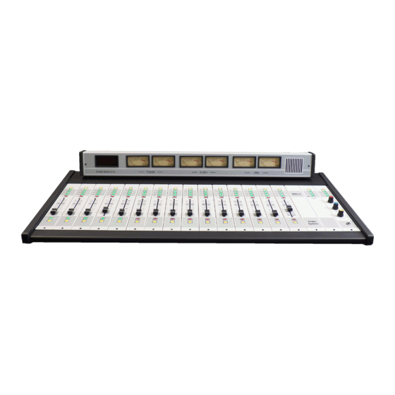
I/O connectors and input trimpots. All I/O is by RJ45 connectors and ten foot wiring is supplied with RJ45 at one end and unterminated at the other end (an expensive option in competing products). The MARC-15 is a very low pro-... - Page 10 The modular mainframe... The MARC-15 is available in a single 15 channel mainframe. The mainframe is a fully enclosed metal cabinet with a rear hinging meter panel. The power supply is an external, autosensing 110-220VAC module. The meter panel contains meters for all three buses, a digi- tal timer, and a built in cue/talkback speaker.
- Page 11 P R O D U C T D E S C R I P T I O N Many modules to choose from... The ‘Output’ module comes standard with the console. The 8, 12, and 15 channel base models can then be configured with any com- bination of input modules that you choose.
- Page 12 Xtreme for the MARC-15 uses the console for audio playback & recording. Where satellite based automation selects between multiple satellite audio feeds, Xtreme for the MARC-15 plays entirely from audio files stored on the hard disk and does not control external sources at all.
- Page 13 Technical features The MARC-15 console by Arrakis Systems inc. is the culmination of > 25 years of leadership in the design of analog and digital Radio consoles and > 15 years as the leader in hard disk automation for Radio.
- Page 14 P R O D U C T D E S C R I P T I O N Electronic Specifications Stereo Line Input Freq Response- +(-).5dB 20-20kHz S/N- -82dB typ, +8dBu in, +8 dBu out THD- .01% typ, +8dBu in, +8 dBu out CMRR- -75dB typ 1kHz Max Input-...
- Page 15 P R O D U C T D E S C R I P T I O N Physical Specifications Arrakis Systems inc. Ext1 Auto Ext1 line line Start Stop Reset Timer Talk to Studio Head phone Monitor Monitor S tudio...
- Page 16 O P E R A T I N G I N S T R U C T I O N S OPERATING INSTRUCTIONS...
-
Page 17: Basic Operation
Basic Operation The MARC-15 console is designed to be very easy to use. The three sets of VU meters follow the Program and Audition and Utility buses. The phone system is very easy to use for off line talking to the caller as well as supporting a Live call in show or Off-line contest call application. - Page 18 O P E R A T I N G I N S T R U C T I O N S Mono mic level Input Modules A/B INPUT SELECTOR The module can select between two microphones. The ‘A’ input is activated when the button is NOT lit.
- Page 19 O P E R A T I N G I N S T R U C T I O N S Stereo Line Level Input Module A/B INPUT SELECTOR The module can select between two stereo input sources. The ‘A’ input is activated when the button is NOT lit. The ‘B’ input is active when the module is lit.
- Page 20 O P E R A T I N G I N S T R U C T I O N S The PC-USB input Module RECORD BUTTON When the module is controlling Arrakis Xtreme soft- ware, this button will start and stop a manual record- ing on the PC computer.
- Page 21 O P E R A T I N G I N S T R U C T I O N S The Telephone Input Module OFF-LINE ASSIGNMENT SWITCH This switch will connect the control room mic to the caller and feed the caller to the console cue system.
- Page 22 O P E R A T I N G I N S T R U C T I O N S The Control Room Monitor system The Control Room Monitor system is the main audio moni- toring system for the studio. It features an input selector switch and a volume level control.
- Page 23 O P E R A T I N G I N S T R U C T I O N S The Headphone system The Headphone (earphone) system in the MARC-15 console is provided so that audio can be listened to while the microphone is active and the monitor speakers are muted.
- Page 24 O P E R A T I N G I N S T R U C T I O N S The Cue system The cue system is designed for monitoring an audio source without placing it on air. This feature is useful for listening to a network feed before bringing it to air, listening to a CD to be certain it is the correct song, etc.
- Page 25 O P E R A T I N G I N S T R U C T I O N S The Timer The MARC-15 console features a 60 minute up timer. The timer is con- trolled by four buttons on the output module.
- Page 26 O P E R A T I N G I N S T R U C T I O N S The VU meters The MARC-15 console features a set of VU meters for all of the console mixing buses (Pgm and Aud and UTL). This simplifies operation and reduces operator error.
-
Page 27: Installation Instructions
I N S T A L L A T I O N I N S T R U C T I O N S INSTALLATION INSTRUCTIONS Getting Started: 4.1 - 4.4 Mainframe: Power Supply: Cabling Gorunding Output Module wiring: 4.9 - 4.14 Input Module wiring: 4.15 - 4.19 PC Setup for USB module: 4.20... - Page 28 Optional cables are available with XLR and RCA on one end for convenience The MARC-15 is quick and easy to install. The meter panel hinges up and back to provide fast access to the RJ45 IO connectors and trimpots. The cabling exits through the bottom rear of the console and can be either through the table or simply out the rear of the console above the tabletop.
- Page 29 CHECK FOR DAMAGE Check all packages and equipment for damage IMMEDI- ATELY upon receipt. If damage is found, contact Arrakis Systems immediate- ly to report the damage. (refer to inside cover of this manual for contact information) c) CAREFULLY GO THROUGH EACH BOX Arrakis inspects every shipment for accuracy.
- Page 30 I N S T A L L A T I O N I N S T R U C T I O N S Before you start a) PHYSICAL SPACE It is important to install the console with sufficient space around it to operate and service the console easily.
- Page 31 CONSUMER SOURCE EQUIPMENT The MARC-15 console is designed to be used with balanced professional & unbalanced consumer type audio source equipment such as CD players, MDs, DAT machines, cassette machines, etc. Unbalanced consumer equipment is designed to perform well in compact studios where audio cables are short.
- Page 32 I N S T A L L A T I O N I N S T R U C T I O N S The Mainframe a) MOUNTING The mainframe is tabletop mounted. It does not require screwing down to the table surface. b) CABLE INGRESS AND EGRESS All cables enter and exit the console at the rear of the mainframe.
-
Page 33: Power Supply
I N S T A L L A T I O N I N S T R U C T I O N S Power Supply Main Power Supply The power supply is an external regulat- ed supply as illustrated below. The DC power connector plugs into the hole in the rear of the mainframe as shown. -
Page 34: Cabling
Shield ground The RJ45 cables supplied with the MARC-15 are shielded. They have a shield drain wire. This drain wire should be grounded on the connector at the equipment end of the cable or at the punch block, not at the console end. - Page 35 I N S T A L L A T I O N I N S T R U C T I O N S Grounding THE BASICS OF GROUND SYSTEMS (IMPORTANT) 1) MANY TYPES OF GROUNDS Because there are several electrical systems in a broadcast facility, there are also several ground systems in the facility. Each ground system fulfills a different function.
- Page 36 1) CONSOLE CHASSIS GROUND The chassis of the MARC-15 is floating. It is NOT connected to ground at all. This is because the power for the console is provided by an external power supply and only low voltages exist in the console. However, to maximize safety, minimize static shock prob- lems, as well as for RF shielding reasons, the console chassis should be grounded.
-
Page 37: Output Module Wiring: 4.9
I N S T A L L A T I O N I N S T R U C T I O N S Monitor amp & Speaker Wiring The console has a balanced, line level monitor audio output that is designed to connect to an external audio power amplifier. The console output will not directly drive speakers. - Page 38 I N S T A L L A T I O N I N S T R U C T I O N S Headphone Wiring The console has a built in headphone amplifier that will drive hi impedance headphones and 8 ohm headphones. The head- phone jack for the amplifier is located at the bottom right of the output module (front right corner of the console).
- Page 39 I N S T A L L A T I O N I N S T R U C T I O N S External Monitor Input Wiring The console has an external audio input for the monitor system. It is usually connected to an off air signal for the radio sta- tion from a radio tuner or modulation monitor.
- Page 40 I N S T A L L A T I O N I N S T R U C T I O N S On Air Light Wiring The console features a sustained reed relay closure for activating an on air light. The reed relay has a maximum current of 50 milliamps and should be used to drive an external relay or other AC devices to drive the on air light.
- Page 41 I N S T A L L A T I O N I N S T R U C T I O N S Talkback (intercom) Wiring The console has two audio inputs for use in talkback: (1) The console has a balanced, line level audio input that feeds the control room monitor speakers (unless muted by a mic) and in the earphones (whether muted or unmuted).
- Page 42 I N S T A L L A T I O N I N S T R U C T I O N S Program Output Wiring These outputs are active, balanced with < 100 ohms output impedance. They are factory calibrated for +4dBu balanced levels. EIA/TIA 568B WIRING STANDARD COLORS 1,2,3,4,5,6,7,8 Wire Color...
- Page 43 I N S T A L L A T I O N I N S T R U C T I O N S Mono mic level Input Module Wiring Connectors Logic ‘B’ ‘A’ Channel Control Logic (Turrets) ‘B’ The pins on the ‘Logic’ connector are used to remote control the mod- ule for applications such as studio talk turrets.
- Page 44 I N S T A L L A T I O N I N S T R U C T I O N S Stereo Line Level Input Module Wiring Connectors Channel Control Logic (Turrets) Logic ‘B’ ‘A’ The pins on the ‘Logic’ connector are used to remote control the mod- ule for applications such as studio talk turrets.
- Page 45 I N S T A L L A T I O N I N S T R U C T I O N S The PC-USB input Module Wiring Connectors Logic Rec USB The RJ45 connector titled ‘RS232 Logic’ wires to a 9 pin RS232 D-sub con- nector as illustrated below 9 Pin RS232 1 nc...
- Page 46 I N S T A L L A T I O N I N S T R U C T I O N S The Telephone Input Module Wiring Connectors Logic Out In a) CONSOLE PHONE INPUT- A telephone hybrid has an audio input and an audio output. The hybrid audio output is the callers voice and is connected to the input on the phone module.
- Page 47 I N S T A L L A T I O N I N S T R U C T I O N S The Studio Monitor Module Wiring Connectors Hdp Mon Ext MUTE LOGIC The ‘Mute Logic’ is a dry contact sustained reed relay closure with a max current of 50 milliamps.
- Page 48 PC Setup The MARC-15 PC-USB input modules have a built in sound card. This enables the console to play audio directly from a Windows PC using Arrakis Digilink-Xtreme software. The console can play audio from the PC, record audio to the PC, and control the start and stop of play on the PC.
-
Page 49: Arc-16Sw
Adding more Inputs to the MARC-15 Console For applications requiring more than the 30 inputs supported by the MARC-15, the ARC-16SW provides up to 16 more stereo inputs that can be selectable to any 3 console channels. The switcher features balanced inputs that are all trim pot adjustable from consumer levels (-10dBu) to professional levels (+4dBu). -
Page 50: Arc-16Sw
I N S T A L L A T I O N I N S T R U C T I O N S ARC-16SW Software Push button Array for Manual Control FEATURES Client/Server network control from ANY studio Manual Pushbutton control of 16 inputs & 3 outputs Customized Labeling of all Inputs &... - Page 51 I N S T A L L A T I O N I N S T R U C T I O N S ARC-16SW 16 in X 3 out Remote Selector for the MARC-15 SWITCHER WIRING a) WHITE MOLEX CONNECTORS NOTE: As viewed looking down on the switcher .
-
Page 52: Basic Calibration
I N S T A L L A T I O N I N S T R U C T I O N S Basic Calibration WARNING The console has been calibrated at the factory to normal +4dBu levels and should not require field calibration. Usually, it is better to adjust the level out of the source device than to adjust the console trim levels. -
Page 53: Output Board Calibration
I N S T A L L A T I O N I N S T R U C T I O N S Output Bd Calibration Remove the jumper to defeat audio HP R HP L MON R MON L into the meter panel cue speaker Output module level adjustments are NOT provided on the front of the output... - Page 54 I N S T A L L A T I O N I N S T R U C T I O N S Input board Jumper Setup Source Input modules have pin jumpers on the PC board Mic Module (only) for rarely used module setup.
- Page 55 I N S T A L L A T I O N I N S T R U C T I O N S INPUT OUTPUT WIRING SUMMARY 1) Mono Mic Input module (MARC-MIC) MIC & STEREO LINE MODULES Channel Control Logic (Turrets) Logic ‘B’...
- Page 56 I N S T A L L A T I O N I N S T R U C T I O N S INPUT OUTPUT WIRING SUMMARY (continued) 5) Studio Monitor Board (MARC-STM) NOTE The ‘Mute Logic’ is a dry contact Earphone Output Monitor Output External Monitor In...
- Page 57 I N S T A L L A T I O N I N S T R U C T I O N S 13.0 Analog Audio Wiring The following sections assume twisted pair, shielded audio cable for all analog wiring. The illustrations demonstrate how to wire balanced and unbalanced analog devices in various configurations.
- Page 58 I N S T A L L A T I O N I N S T R U C T I O N S 13.3 Transformer Balanced Output to Balanced Console Input Transformer sources require a fixed impedance for proper performance. The console input impedance is high compared to the impedance of most transformers and will require a resistor to match the trans- former.
- Page 59 I N S T A L L A T I O N I N S T R U C T I O N S 13.5 Use of an Isolation Transformer to convert an Unbalanced Source into a Balanced Source In some situations, an isolation transformer is required for RF or ground loop isolation where the source output is unbalanced.
- Page 60 I N S T A L L A T I O N I N S T R U C T I O N S 13.6 Console Balanced Output to Balanced Input Balanced inputs and outputs are the best method to reject hum CONSOLE ACTIVE BALANCED OUTPUT...
- Page 61 I N S T A L L A T I O N I N S T R U C T I O N S 13.8 Console Balanced Output to Transformer Input Transformer sources require a fixed impedance for proper performance. The console output impedance is low compared to the impedance of most transformers and will require a resistor to match the transformer.
-
Page 62: Ground Loops 4.34
I N S T A L L A T I O N I N S T R U C T I O N S Ground Loops a) A GROUND LOOP CAUSES 60 CYCLE HUM A ground loop exists when there is more than one ground path between two pieces of elec- tronic equipment. - Page 63 I N S T A L L A T I O N I N S T R U C T I O N S Ground Loops (continued) e) BREAKING A GROUND LOOP WITH AN AUDIO ISOLATION TRANSFORMER In cases where the ground loop can not be broken due to a 3rd wire safety ground as the sec- ond part of the ground loop, an audio isolation transformer can be inserted into the audio sig- nal line.
-
Page 64: Dhd-Live
DHD-LIVE FOR THE MARC CONSOLE... -
Page 65: Getting Started
Getting Started Included with an ARC series console (with a USB channel) is a free copy of DHD-Live. This software is the ultimate live assist tool for anyone who wants to put on a dynamic and powerful live show. It includes features that give you unprecedented customization and flexibility. We are confident that you will love this software. - Page 66 S E R V I C E & M A I N T E N A N C E SERVICE & MAINTENANCE INSTRUCTIONS...
- Page 67 DESIGNED FOR MODULAR PART REPLACEMENT The MARC-15 console is designed for modular replacement rather than field repair. The power supply is external and plug in. Most ICs are plug in. The rotary faders, and meters are plug in. A small amount of disassembly is required to reach most parts. Diagrams on the fol- lowing pages explain the required disassembly.
-
Page 68: Opening The Console
The motherboards are accessed by removing the modules from the console. 2) ACCESSING THE INTERIOR OF THE VU METER PANEL The VU meter panel is opened by removing the screw at the left and right front of the panel. Program Audition Utility Arrakis Systems inc. ACCESS SCREWS... - Page 69 S E R V I C E & M A I N T E N A N C E Removing an Input Module The input modules have a single bus ribbon cable that connects them to the motherboard. Care should be taken when removing or reinstalling this cable.
- Page 70 S E R V I C E & M A I N T E N A N C E Removing the Studio Monitor Module The studio monitor module has two bus ribbon cables that connects it to the motherboard. Care should be taken when removing or reinstalling these cables.
- Page 71 S E R V I C E & M A I N T E N A N C E Removing the Output Module The output module has four cables that connect it to the motherboard and the VU meter bridge. While none of the cables are interchangeable, care should be taken when Reset Ext1 removing or reinstalling these cables.
- Page 72 (4) Unplug the pot from the motherboard. KNOB to reveal a lock LOCK nut. Unscrew the lock nut to remove To put a new rotary fader in place: the knob Reverse the removal procedure Arrakis Systems inc. Ext1 Auto Ext1 line line Start Stop Reset...
- Page 73 S E R V I C E & M A I N T E N A N C E Replacing ICs ICs must be replaced with care. Most ICs in the console are socketed so that they can be replaced. When replacing an IC, be careful to not bend legs under the IC or outside the socket.
- Page 74 S E R V I C E & M A I N T E N A N C E Electronic Block Diagram RJ45 (8 wire) Mic module Channel On, Off, Tally Logic Trim Cough, Talkback CONTROL ROOM HEADPHONE JACK MONITOR OUTPUT PL-PR-AL-AR-UL-UR-Q-TB Logic Logic...
- Page 75 S E R V I C E & M A I N T E N A N C E Mic Module Start Relay The MARC-15 console is designed for modular replace- ment rather than component level field repair. The con- Stop Relay sole is modular and modules can be replaced for imme- diate repair.
-
Page 76: Stereo Line Module
S E R V I C E & M A I N T E N A N C E Stereo Line Module The MARC-15 console is designed for modular ‘A’ input Start Relay replacement rather than component level field trimpots repair. - Page 77 S E R V I C E & M A I N T E N A N C E PC-USB module The MARC-15 console is designed for modular USB chip replacement rather than component level field PCM2900 Record repair. The console is modular and modules can be input amp replaced for immediate repair.
- Page 78 S E R V I C E & M A I N T E N A N C E Phone Module Input The MARC-15 console is designed for modular trimpot replacement rather than component level field Start Relay repair. The console is modular and modules can be Output replaced for immediate repair.
- Page 79 S E R V I C E & M A I N T E N A N C E Studio Monitor Module The MARC-15 console is designed for modular Ext 1 Monitor Left replacement rather than component level field Input Output trimpot repair.
- Page 80 S E R V I C E & M A I N T E N A N C E Output Module The MARC-15 console is designed for modular replacement rather than com- Headphone Output amps Monitor NE5532 ponent level field repair. The console is...
- Page 81 Arrakis Systems does not warranty equipment that has failed due to improper installation, abuse, or acts of nature. It is solely at the discretion of Arrakis Systems as to whether a part is defective under warranty conditions.
- Page 82 S E R V I C E & M A I N T E N A N C E Factory Service (continued) Warranty Replacement of Parts To have a part replaced under warranty, you must: 1) Provide a valid product serial number that is within the warranty period 2) Contact the Arrakis customer service department and describe what parts need replacement and the circumstances of the failure.
Need help?
Do you have a question about the MARC-15 and is the answer not in the manual?
Questions and answers