Table of Contents
Advertisement
Quick Links
Advertisement
Table of Contents

Summary of Contents for Ubiquiti UVC-Pro-C
- Page 1 Cable Accessory Model: UVC-Pro-C...
-
Page 2: Package Contents
Thank you for purchasing the Ubiquiti Networks UniFi® Video ™ Camera PRO Cable Accessory, model UVC-Pro-C. The accessory is designed for use with the UVC PRO. In addition to the convenient Reset button, the UVC PRO Cable Accessory provides Ethernet, Audio In/Out, and mFi RJ45 connectors. -
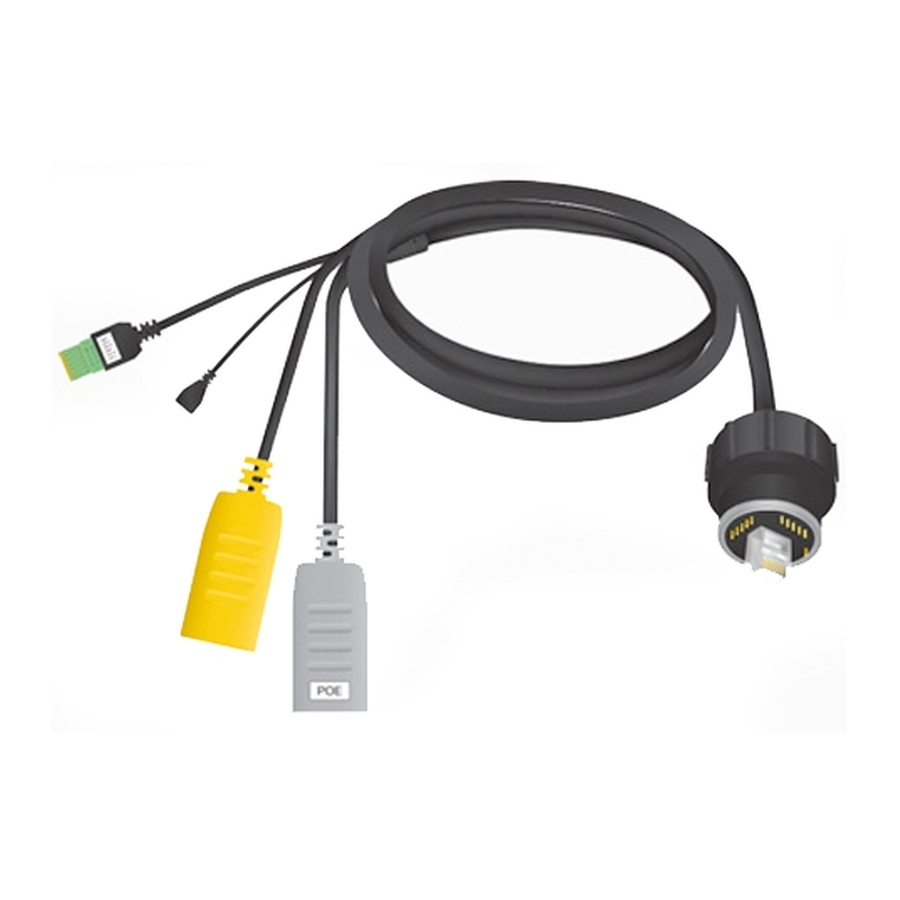
Page 3: Cable Overview
Cable Overview Audio In/Out Reset Button UVC PRO Coupling RJ45 Port PoE Port Connection Description Features two-channel audio input Audio and one-channel audio output to a In/Out speaker. To reset to factory defaults, press and hold the Reset button for more than Reset Button 10 seconds while the UVC PRO is already powered on. -
Page 4: Cable Installation
Cable Installation 1. Install the waterproofing O-Ring inside the waterproof gland of the UVC PRO cable. 2. Align the RJ45 connector of the UVC PRO Coupling with the Ethernet port of the waterproof gland. Ensure the RJ45 pin connections are facing each other. *640-00107-01* 640-00107-01... - Page 5 3. Press the UVC PRO Coupling into the waterproof gland and ensure the alignment notches are lined up. 4. Secure the connection by turning the coupling nut clockwise. Do not use any tools. Only hand-tighten the coupling nut.
- Page 6 Audio In/Out Connection The Audio In/Out Connection provides one-channel output and two-channel (stereo) input. Use the included terminal block to connect your audio wires. The audio wires should be 20 - 28 AWG, solid single-core wires. Speaker 8Ω, 1W 2 Channel Line-In Audio Wiring Diagram 1.
- Page 7 mFi Connection Connect to an mFi mPort to integrate the UVC PRO into an mFi system. The UVC PRO can be used as a digital sensor for machine-to-machine automation, sensoring, and monitoring. 1. Connect an Ethernet cable to the yellow mFi RJ45 port. 2.
- Page 8 3. Launch the mFi Controller. 4. Click the Settings icon of the mPort. 5. In the Configuration tab of the mPort Settings window, click the Add icon and select Ubiquiti UVC PRO from the device type drop-down list. Note: Ensure the latest version of mFi Controller is installed.
-
Page 9: Connecting Power Over Ethernet
Connecting Power over Ethernet 1. Connect an Ethernet cable to the gray PoE port. 2. Connect the other end of the Ethernet cable to one of the following: • PoE Adapter Connect to the Ethernet port labeled POE on the UVC PRO PoE Adapter. •... - Page 10 3. Connect an Ethernet cable from your LAN to the Ethernet port labeled LAN on the PoE Adapter. 4. Connect the other end of the power cord to a power outlet. The Power LED should light up on the UVC PRO.
-
Page 11: Safety Notices
Safety Notices Read, follow, and keep these instructions. Heed all warnings. Only use attachments/accessories specified by the manufacturer. WARNING: Do not use this product in location that can be submerged by water. WARNING: Avoid using this product during an electrical storm. -
Page 12: Limited Warranty
UBIQUITI NETWORKS under normal use and operation. UBIQUITI NETWORKS’ sole and exclusive obligation and liability under the foregoing warranty shall be for UBIQUITI NETWORKS, at its discretion, to repair or replace any Product that fails to conform to the above warranty during the above warranty period. - Page 13 Products being received at UBIQUITI NETWORKS’ facility freight prepaid in accordance with the RMA process of UBIQUITI NETWORKS. Products returned without an RMA number will not be processed and will be returned freight collect or subject to disposal.
-
Page 14: Limitation Of Liability
Limitation of Liability EXCEPT TO THE EXTENT PROHIBITED BY LOCAL LAW, IN NO EVENT WILL UBIQUITI OR ITS SUBSIDIARIES, AFFILIATES OR SUPPLIERS BE LIABLE FOR DIRECT, SPECIAL, INCIDENTAL, CONSEQUENTIAL OR OTHER DAMAGES (INCLUDING LOST PROFIT, LOST DATA, OR DOWNTIME COSTS), ARISING OUT OF THE USE, INABILITY TO USE, OR THE RESULTS OF USE OF THE PRODUCT, WHETHER BASED IN WARRANTY, CONTRACT, TORT OR OTHER LEGAL THEORY, AND WHETHER OR NOT ADVISED OF THE POSSIBILITY OF... - Page 15 Additional UVP-Pro Accessories UVC-Pro-M Large Pole Mount Accessory • Industrial-Grade Metal Mount • Fits up to160 mm Diameter Poles • Mounts One or Two Cameras Avaiable UniFi Video Products UVC-NVR Stand-Alone UniFi Video Appliance • UniFi Video Controller • Network Video Recorder •...
- Page 16 . u b n t . c o m ©2014 Ubiquiti Networks, Inc. All rights reserved. Ubiquiti, Ubiquiti Networks, the Ubiquiti U logo, the Ubiquiti beam logo, ToughCable, ToughSwitch, and UniFi are trademarks or registered trademarks of Ubiquiti Networks, Inc.
Need help?
Do you have a question about the UVC-Pro-C and is the answer not in the manual?
Questions and answers