
Summary of Contents for ROYALL 6150
- Page 1 Installation OUTDOOR PRESSURIZED BOILER Models: 6150, 6200, 6300, 6490 INDOOR PRESSURIZED BOILER Models: 6130NS, 6150NS, 6200NS, 6300NS, 6490NS www.royallfurnace.com 325 South Park Street Reedsburg, WI 53959 Phone 608-768-8508...
-
Page 2: Hazard Definitions
Thank you for purchasing a ROYALL pressurized Solid Fuel appliance. Boilers are a quality Solid Fuel Appliance designed to effectively heat structures. Please read and follow all safety instructions to ensure optimal performance. The installation and operation of the is quite simple. Nevertheless, we recommend that the instructions be carefully read and followed. - Page 3 PRODUCT REGISTRATION CARD Warranty is in effect from the date of purchase upon receipt of this card. NAME STREET ADDRESS CITY STATE ZIP CODE PHONE EMAIL ADDRESS DATE OF PURCHASE MODEL NUMBER SERIAL NUMBER DEALER CITY STATE Reason for choosing Royall over other brands __Price __Features __Safety __Previously owned Royall __Recommended to you __Other PRODUCT REGISTRATION CARD...
- Page 4 Place Stamp Here Brand Products 325 South Park Street Reedsburg, WI 53959 Place Stamp Here Brand Products 325 South Park Street Reedsburg, WI 53959...
-
Page 5: Table Of Contents
CONTENT GENERAL SAFETY..............................Pg PRESSURIZED BOILER SPECIFICATIONS..................Pg PRODUCT DESCRIPTION........................Pg INSTALLATION INSTALLATION TIPS..........................Pg INSTALLATION PLACEMENT......................Pg CONTENTS............................Pg SHROUD INSTALLATION........................Pg 11 FIREBRICK INSTALLATION........................Pg 12 INDOOR BOILER INSTALLATION: VENTING..................Pg 13 PLUMBING CONNECTIONS........................ Pg 15 COMPONENT ASSEMBLY........................Pg 16 ELECTRICAL............................ -
Page 6: Safety
SAFETY NOTICE ALL STATE or LOCAL CODES take precedence and MUST be observed. These models have been certified compliant to UL 391-06 through independent testing. Additionally, some of these recommendations align with the National Fire Protection Assign. Code 211. Before installing or starting operation, read and familiarize yourself with all instructions. -
Page 7: Pressurized Boiler Specifications
NUMBER 6130 130,000 6.25 cubic ft 26” 10 X 14 6“ 23 gal 24 X 44 X 38 6150 150,000 8.1 cubic ft 26” 10 X 14 6“ 35 gal 26 X 51 X 38 45 X 60 X 77 1415 INDOOR &... -
Page 8: Product Description
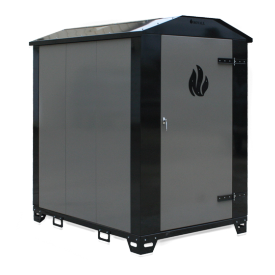
PRODUCT DESCRIPTION Indoor/Outdoor Solid Fuel Boilers are designed to burn either seasoned, split cord wood or coal. A water circulating pump moves the heated water to a heat exchanging device. This can be a base board radiator, fi nned based board radiator, water to air exchanger, or existing boiler system; with the correct safety apparatus installed to local codes. -
Page 9: Installation Tips
INSTALLATION TIPS AVOIDING AIR LOCKS All ROYALL Solid Fuel Boilers are designed not to exceed 30 psi, and will vent to the atmosphere if necessary. Air trapped in the lines prevents circulation. Poor circulation is a common start up problem. Reduced fl ow can be diffi cult to detect because the pipes will feel hot. -
Page 10: Installation Placement
INSTALLATION PLACEMENT IMPORTANT NOTE • CHECK WITH INSURANCE COMPANY PRIOR TO INSTALLATION. IT IS THE OWNER’S RESPONSIBILITY TO ENSURE THAT THE APPLIANCE IS ACCEPTABLE TO THEIR INSURANCE CARRIER. • VERIFY LOCAL CODES AND ORDINANCES PRIOR TO INSTALLATION. IT IS THE OWNERS RESPONSIBILITY TO ENSURE THAT THE APPLIANCE MEETS ALL LOCAL CODES AND ORDINANCES WHICH TAKE PREEDENCE AND MUST BE OBSERVED PROVIDING THEY ARE MORE RESTRICTIVE. -
Page 11: Contents
CONTENTS INSTALLATION: CLEARANCES – INDOOR MODELS The Indoor boiler must be installed with these minimum clearances from NON-COMBUSTIBLE surface: Front = 30”/ Back = 30” / Sides = 12” The Indoor boiler must be installed with these minimum clearances from any COMBUSTIBLE surface: Front = 48”/ Back = 30”... - Page 12 CONTENTS (CONT.) INSTALLATION: INSPECTING CONTENTS BOXED COMPONENTS SHIPPED LOOSE INSIDE (component illustrations located in repair parts section) ROYALL INDOOR BOILER Fire Brick Aquastat Pressure and Temperature Gauge Draft blower and gasket Pressure Relief Valve ...
-
Page 13: Shroud Installation
SHROUD INSTALLATION Attach Shroud mount corners to Boiler using supplied hardware. Each corner is designed to fi t a specifi c corner of the unit. Attach Shroud side panels to corners. Panels will fi t inside the corners. Install Shroud top. Top must be installed before aquastat is installed. -
Page 14: Firebrick Installation
Repeat for 2nd side. Model 6130 MODEL 6150 & 6200 (12) Full & (2) Cut Bricks Starting in the BACK of the unit, place ½ brick on end, then add 4 full brick on end. Last lay 2 full bricks side down. -
Page 15: Indoor Boiler Installation: Venting
INDOOR BOILER INSTALLATION: VENTING All single wall chimneys must be at least 18” from any combustible surface. Fire can DANGER result, causing severe personal injury, death, or substantial property damage. A major cause of chimney-related fi res is failure to maintain required clearances DANGER (air spaces) to combustible materials. - Page 16 INSTALLATION: VENTING CHIMNEY HEIGHT To prevent downdrafts, chimney, or vent without a listed cap should extend at least 3 feet above the highest point where it passes through a roof and at least 2 feet higher than any portion of a building within a horizontal distance of 10 feet.
-
Page 17: Plumbing Connections
PLUMBING CONNECTIONS SIZE OF BOILER FITTINGS Front View Back View September 2012 Page 15... -
Page 18: Component Assembly
COMPONENT ASSEMBLY INDOOR BOILER : CONNECTIONS (OUT DOOR BOILERS ASSEMBLED AT FACTORY, INDOOR UNITS SHIPPED WITH COMPOTES BOXED AND STORED IN FUEL CHAMBER FOR PROTECTION DURING SHIPPING) INSTALL COMPONENTS AS FOLLOWS AND LOCATE PER REFERENCE CHART AND DIAGRAM ON PREVIOUS PAGE. PRESSURE TEMPERATURE GAUGE (#2) •... - Page 19 PRESSURE RELIEF VALVE (#3) (CONT.) • No shutoff valve shall be installed between the relief valve and boiler, or in the discharge line. Do not plug or place any obstruction in the discharge line. • Test the operation of the valve after fi lling and pressurizing system by lifting the lever. Ensure the valve discharges freely.
-
Page 20: Electrical
ELECTRICAL ELECTRICAL INSTALLATION MUST COMPLY WITH • National Electrical Code and any other national, state, provincial or local codes or regulations. • In Canada, CSA C22.1 Canadian Electrical Code Part 1, and any local codes. Appliance must be electrically grounded as required by National Electrical Code ANSI/NFPA 70–latest edition. Ensure ground wiring is installed per wiring diagram. - Page 21 ELECTRICAL (CONT.) INSTALLATION: SETTING THE ANALOG AQUASTAT ANALOG IMMERSION AQUASTAT (Indoor units -Outdoor factory installed) 1) Loosen screw on right side of case and remove cover. SET the high limit set point knob to the desired shut off water temp (never above 195 degrees). NOTE these units have a built in 10 degree drop diff erential.
-
Page 22: Aquastat Control Setting
AQUASTAT CONTROL SETTING September 2012 Page 20... -
Page 23: Electrical Diagrams
ELECTRICAL DIAGRAMS INSTALLATION: BOILER PIPING 1) BOILER DRAIN VALVES Drain valves are recommended to assist in fi lling and purging air. See chart in connection section in door and out door locations Pipe in Tee at bottom of return (“Cold”) pipe. Pipe in Tees at top of both return (“Cold”) and supply (“Hot”) pipes. -
Page 24: System Plumbing
SYSTEM PLUMBING INSTALLATION: GENERIC SYSTEMS The system Diagrams provided are only suggested schematics for generic systems and do not CAUTION purport to show all required components necessary to meet all required codes. Complex systems should be designed by a professional heating system. GENERAL COMMENTS PIPING AT THE APPLIANCE Base Board... -
Page 25: Typical System Schematics
TYPICAL SYSTEM SCHEMATICS OPERATION 1) The solid boiler pump runs constantly, circulating water through the solid fuel boiler via the primary- secondary Tees. If the thermostat calls for heat, the existing boiler will start the boiler pump. The burner will not fi re as long as the start temperature is above the aquastat setting on the existing boiler. - Page 26 TYPICAL SYSTEM (CONT.) OPERATION 1) Water circulates continuously through the solid fuel boiler. 2) When the thermostat calls, either the zone pump turns on or the existing boiler turns on it’s pump, allowing water to fl ow to the baseboard. PIPING INSTALLATION 1) Ensure that the expansion tank is not isolated from the Boiler.
- Page 27 TYPICAL SYSTEM SCHEMATICS (CONT.) 2) LOW TEMP RADIANT or MIXED TEMP SYSTEM Low temperature radiant systems require some sort of tempering device, most commonly a thermostatic mixing valve. Low temperature and high temperature applications can be easily accommodated by the solid fuel boiler.
-
Page 28: Initial System Fill
INITIAL SYSTEM FILL 1) FILL, ISOLATE, AND PRESSURE TEST Although the solid fuel boiler is factory pressure tested, it should be tested in the fi eld to ensure that no damage has occurred during shipping. Isolate the solid fuel boiler from the system prior to pressure testing. - Page 29 INITIAL SYSTEM FILL(CONT.) 2) TEST WATER QUALITY Test system water pH to determine if water treatment is necessary. Heating system water pH of 8.5 to 11.0 is recommended. Swimming pool pH test kits are readily available from other sources. Consult local water treatment companies for unusually hard water areas (above 7 grains hardness) or low pH water conditions (below 7.0).
-
Page 30: First Fire
FIRST FIRE OPERATION - FOLLOW ALL SAFETY PRECAUTIONS BEFORE STARTING A FIRE • ENSURE the isolation valves are open. • Start the pump. The pump is lubricated with water. DO NOT run dry. • Cycle the FAN switch to check for proper draft blower operation. •... -
Page 31: Burning With Wood
BOILER CONTROL (CONT.) 8) AUXILIARY “DUMP ZONE” A safety limit aquastat should be used. Set the safety limit aquastat below water temperature. In a hot water base board system the zone valves should open and the circulating pump should start. Reset to 15°... -
Page 32: Burning With Coal
BURNING WITH COAL BURNING COAL A barometric draft damper MUST be installed between the solid fuel boiler and the chimney. Determine and research what types of coal are commonly available in your area. You will get more heat and longer burn periods if you are educated on how to burn the type of coal available to you. - Page 33 BURNING WITH COAL (CONT.) • The solid fuel boiler will maintain water temperature based on the aquastat settings. • Room temperature is controlled by a thermostat in the room. • The loading door and ash removal door must tightly shut and the seals maintained in good condition during operation, otherwise overheating will occur.
-
Page 34: Emergency Actions
EMERGENCY ACTIONS OVER HEATING 1) Manually turn off the draft fan at the fan switch (place switch in OFF position). 2) The pump must have power to remove heat from the appliance. 3) Turn the thermostats fully up in the structure being heated by boiler to remove heat from the appliance as fast as possible. -
Page 35: Maintenance
MAINTENANCE Keeping the solid fuel boiler in good repair will result in more effi cient operation and longer appliance life. You are responsible for safely maintaining the unit. Follow the Service and Maintenance procedures given throughout this manual and in component literature shipped with the appliance. Failure to perform the service and maintenance could result in damage to the boiler or system. - Page 36 MAINTENANCE (CONT.) BEGINNING OF SEASON • Chimney: Remove cap from chimney. Inspect chimney. Ensure chimney is not blocked (check for animal or bird nests). • Loading Door: Oil door hinges and latch. Inspect gaskets. Verify that door seals tightly (apply thin coat of lipstick to loading fl ange, shut door, reopen and inspect marking on the gasket).
- Page 37 MAINTENANCE (CONT.) **PRESSURE (SAFETY) RELIEF VALVE ** Failure to re-inspect the pressure relief valve as directed could result in unsafe pressure buildup, which can result in severe personal injury, death or substantial property damage. AT LEAST ONCE A YEAR: Pressure relief valves must be operated to ensure that waterways are clear. Certain naturally occurring mineral deposits may adhere to the valve, rendering it inoperative.
-
Page 38: Trouble Shooting
TROUBLE SHOOTING 1) PROBLEM: LOSING PRESSURE IN SYSTEM. A) Air bleeding out of system will cause pressure loss. When the appliance is fi rst fi lled, it may take 3- 4 days to purge all the air. Add water as needed until pressure stabilizes. B) An undersized expansion tank will cause large pressure changes as the system water temperature changes. - Page 39 TROUBLE SHOOTING (CONT.) 4) PROBLEM: WATER TEMPERATURE DOES NOT REACH FAN CONTROL AQUASTAT SETTING. (DRAFT FAN RUNS CONTINUOUSLY.) A) Wood may be too wet or green. Try mixing woods. B) Check for obstructions in draft fan. C) A defective solenoid may cause fl apper on fan not to open when fan comes on. D) A partially clogged chimney or exhaust plenum may be restricting air fl ow in the appliance.
-
Page 40: Replacement Parts Listing
TROUBLE SHOOTING (CONT.) 7) PROBLEM: SMOKE “PUFFS” FROM THE UNIT A) Wood may be too wet or green. Try mixing woods. B) Check for obstructions in draft path (Blower, Chimney Connector, Chimney). C) A partially clogged chimney or exhaust plenum may be restricting air fl ow in the appliance. D) A buildup of ashes in the ash trough can restrict the exhaust of combustion air. - Page 41 REPLACEMENT PARTS LISTING (CONT.) 3 / 8 - 1 6 x 1 1 / 2 H H C S 3 / 8 - 1 6 N u t C a s t B a f f l e R o c k e r G r a t e S h a k e r F r o n t H a n d l e...
- Page 42 REPLACEMENT PARTS LISTING (CONT.) D a m p e r P l a t e 3 / 1 6 x 2 1 / 2 C o t t e r P i n D a m p e r R o d S p r i n g H a n d l e Ref.
- Page 43 REPLACEMENT PARTS LISTING (CONT.) P R E S S U R E / T E M P G A U G E P R E S S U R E R E L I E F V A L V E A Q U A S T AT W / W E L L F U E L D O O R P O S I T I V E S H U T O F F...
-
Page 44: Warranty
WARRANTY ON ROYALL SOLID FUEL APPLIANCES Warranty On Solid Fuel Appliances ROYALL Solid Fuel Appliances are warranted by ROYALL to the original user against defects in workmanship under normal use, from the date of purchase. This warranty is subject to the condition that the ROYALL Product(s) must have been installed in accordance with manufacturer’s instructions.