Table of Contents
Advertisement
Advertisement
Table of Contents

Subscribe to Our Youtube Channel
Related Manuals for Aopos Anypos600

Summary of Contents for Aopos Anypos600
- Page 1 Anypos600 Point of Service Anypos600 User Manual AOPOS SYSTEMS, S.A.
-
Page 2: Trademark Acknowledgments
Trademark Acknowledgments AOPOS SYSTEMS, S.A. All rights reserved. Other product names mentioned herein may be trademarks or registered trademarks of their respective companies. AOPOS claims no interest in trademarks other than its own. - Page 3 Anypos600 Point of Service Federal Communications Commission (FCC) This equipment has been tested and found to comply with the limits for a Class A digital device, pursuant to Part 15 of the FCC Rules. These limits are designed to provide reasonable protection against harmful interference in a residential installation.
-
Page 4: Safety Information
Anypos600 Point of Service Safety information Before installing and using the Anypos, take note of the following precautions: Read all instructions carefully. Do not place the unit on an unstable surface, cart, or stand. Do not block the slots and opening on the unit, which are provided for ventilation. -
Page 5: Table Of Contents
Anypos600 Point of Service TABLE OF CONTENTS Chapter 1 INTRODUCTION…..............1 About the Product………………………………………………...………1 Specification………………………………………….…………………..1 Unpacking the Anypos……………..………………………………...3 Checking the packaging list………………………………………………3 Identifying Components………………………………………………….4 Removing the bottom cover…………………………………………..….6 Attaching the customer display…………………………………………..6 Attaching the second monitor……………………………………………7 Adjusting display angles………………………………………………….8 Connecting peripheral devices………………………………………..…..8 Powering the Anypos on and off……………………………………..9... -
Page 6: Chapter 1 Introduction
Anypos600 Point of Service CHAPTER 1 INTRODUCTION Welcome Thank you for purchasing our powerful Anypos! With this manual is to help you operate and maintain the Anypos. About the Product Anypos is an innovational design from Point of Sale terminals and Kiosk with over decade of... - Page 7 Anypos600 Point of Service Serial port 4 (with 5V/12V) Parallel port KB/MS port Back LAN port 10/100 Base-T Panel VGA port Ports Audio jacks Cash drawer port 1(share) Modem port(RJ11) 1(share) Dimension (mm) 370(l) X 280(w) X 340(h) max Weight (standard) 8.5 Kg...
-
Page 8: Unpacking The Anypos
Anypos600 Point of Service Unpacking the Anypos The Anypos and cable accessories are packed in a cardboard carton with foam padding for protection during shipping. Carefully unpack the Anypos as the picture below. NOTE: Please keep the packing materials if you need to ship the Anypos in the future. -
Page 9: Identifying Components
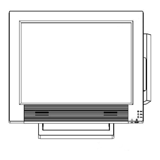
Anypos600 Point of Service Identifying Components This section describes the parts and connectors on the Anypos. Front-right view DESCRIPTION 15-inch TFT LCD and touch screen Magnet Stripe Reader ( MSR ) Power LED HDD LED IC Card LED Power button... - Page 10 Anypos600 Point of Service DESCRIPTION COMBO CDROM Customer Display IC Card Reader Rear Cover Customer Display Base Bottom Cover Base Bottom Panel Ports (Anypos616) DESCRIPTION PS2 mouse port Parallel port (LPT) +12V DC +12V Output Modem or cash drawer port (RJ11) 10/100 NIC port1&2...
-
Page 11: Removing The Bottom Cover
Anypos600 Point of Service NOTE: 、 Remove the bottom cover before you connect the peripherals to the bottom Connectors. The bottom panel ports may be different from others depending on the specification and types. 、 The default setting of VFD customer display port(RJ45) is COM2 or COM4. If you want to use DB9 port instead of RJ45, the special wire is needed. -
Page 12: Attaching The Second Monitor
Anypos600 Point of Service 1. Connect the customer display cable to Customer Display port on the bottom panel 2. Secure the display with four supplied screws. Attaching the second Monitor 1. Connect the signal cord of the second monitor to the VGA... -
Page 13: Adjusting Display Angles
Anypos600 Point of Service Adjusting display angles The main display can be tilted back from 10 degrees to 66 degrees. (See the picture below.) Connecting peripheral devices Peripheral devices such as a printer or scanner can be connected to the Anypos. Refer to the user manual of the device you are connecting for instructions on installing drivers where needed. -
Page 14: Powering The Anypos On And Off
Anypos600 Point of Service Powering the Anypos on and off 1. Remove the bottom cover. Connect the power cable to the power connector on the Anypos , Connect the AC adapter to an electrical outlet.(only for External Adapter) 3. Press the power button on the underside of the display panel. -
Page 15: Chapter 2 Bios Setup Utility
Anypos600 Point of Service CHAPTER 2 BIOS SETUP UTILITY The BIOS (Basic Input and Output System) Setup Utility displays the system's configuration status and provides options to set system parameters. The parameters are stored in battery-backed-up CMOS RAM that saves this information even when the power is turned off. -
Page 16: Main Screen
Anypos600 Point of Service conflicts, making changes to the Power Management configuration, and changing the User or Supervisor password, etc. Main Screen When you start the Setup Utility, the main menu appears. See the picture below. Standard CMOS features Use this menu to set basic system configuration. -
Page 17: Advanced Chipset Features
Anypos600 Point of Service Disable this sequence. Disabled Default setting:USB-ZIP/ CD-ROM/HDD-0 Advanced Chipset Features This menu is used for optimizing the chipset functions. Boot Display This setting refers to the type of display being used with the system Default setting: CRT+LEP ... -
Page 18: Pc Health Status
Anypos600 Point of Service ReQuests) and DMAs (Direct Memory Access). PC Health Status This section shows the status of your CPU, fan, warning for overall system status. Frequency/Voltage Control Use this menu to set DRAM voltage, DRAM clock, and DRAM timing, etc. -
Page 19: Chapter 3 Driver Installation
Manual and peripheral instruction DOSNET Client software to Access Server for DOS. All above can be downloaded from our website (www.aopos.com) Driver Installation Please install the driver utilities as the following sequences, otherwise it may result in unpredictable circumstances, such as: unstable system, display mistake, etc, and even you may... - Page 20 Anypos600 Point of Service have to reinstall the operating system. Driver Installation of Chipset The Chipset Driver is on \DRIVERS\CHIPSET subdirectory, run SETUP.EXE and install driver on prompt, after completing installation, reboot the computer. Driver Installation of VGA The VGA Driver is on DRIVERS\VGA letter, run SETUP.EXE and install driver on prompt, after completing the installation reboot the computer.
- Page 21 Anypos600 Point of Service A). If Windows start the New Hardware Wizard Choose Next. Select "Search for the best driver for your device (Recommended)" and Choose Next. When a list of search locations is displayed, place a checkmark on "Specify a location"...
-
Page 22: Chapter 4 System Testing
Anypos600 Point of Service CHAPTER 4 SYSTEM TESTING This chapter gives you detailed explanation of system testing functions. About Testing The CHECK.EXE is a test program in TOOLS subdirectory in your CD or your HDD, which is for test of the Printer, the CustDisplay, the Keyboard, the Drawer, MSR, Scanner, IC Card Reader and Ports. -
Page 23: Setup The Touchscreen
Anypos600 Point of Service Ensure the printer prints the same as the typing on the screen. Return from the sub-menu press Esc. CustDisplay: Tests the customer display. Ensure the customer display shows the same numbers and characters as input on prompt. Return by pressing Esc. - Page 24 Anypos600 Point of Service General User can select the controller list in the windows to do configuration for it. Tools 4 Points Calibration:It needs calibration before the touchscreen work accurately. Clear and Calibrate:To erase the 25 points calibration/linearization parameters and...
- Page 25 Anypos600 Point of Service Linearization:is used to compensation the touchscreen linearity. Draw Test:is used for accuracy and performance check. Setting Beep: 1) Beep On Touch: Linearization Style:Touchkit utility provides user with 9 points and 25 points calibration for linearization.
- Page 26 Anypos600 Point of Service...
-
Page 27: Chapter 5 Troubleshooting
Anypos600 Point of Service CHAPTER 5 Troubleshooting Often after time spent troubleshooting, the problem is traced to something as simple as a loose connection. Check the following before proceeding to the problem-specific solutions. The Power-On Self Test The Power-On Self Test (POST) runs every time you turn on or reset the computer. The POST checks memory, the mainboard, the display, the keyboard, the disk drives, and other installed options. -
Page 28: General Problems
Anypos600 Point of Service HARD DISK(S) FAIL Unable to recalibrate fixed Have the Anypos (10) disk. serviced. KEYBOARD IS The keyboard is locked and Have the Anypos LOCKED OUT - the key-board controller is serviced. UNLOCK THE KEY pulled low. -
Page 29: Having The Anypos Serviced
Anypos600 Point of Service Check the cable connection. Check the mouse or You cannot use a mouse or keyboard with another computer to see if it works. If the keyboard. same problem occurs, replace the mouse or keyboard. Otherwise, have the Anypos serviced. -
Page 30: Chapter 6 Service And Maintenance
1 year warranty. 2. Online Service You can obtain help from AOPOS when you are unable to solve the problem. Please contact our ser and Maintenance Department for any requires. Hotline:400-708-9898. Our service engineers will provide the most efficient help, or visit our website: www.aopos.com to obtain help online.
Need help?
Do you have a question about the Anypos600 and is the answer not in the manual?
Questions and answers