Table of Contents
Advertisement
Quick Links
CAUTION: This stabilized antenna system is designed to be used with transmit/receive equipment
manufactured by others. Refer to the documentation supplied by the manufacturer which will
describe potential hazards, including exposure to RF radiation, associated with the improper use of
the transmit/receive equipment. Note that the transmit/receive equipment will operate independently
of the stabilized antenna system. Prior to work on the stabilized antenna system, the power to
the transmit/receive system must be locked out and tagged.
When the transmit/receive system is in operation, no one should be allowed anywhere within the
radiated beam being emitted from the reflector.
The ultimate responsibility for safety rests with the facility operator and the individuals who
work on the system.
Sea Tel, Inc.
4030 Nelson Avenue
Concord, CA 94520
Tel: (925) 798-7979
Fax: (925) 798-7986
Email: seatel@seatel.com
Web:
www.seatel.com
July 9, 2007
INSTALLATION AND OPERATION
MANUAL FOR SEA TEL BROADBAND-AT-SEA
TRANSMIT / RECEIVE SYSTEM
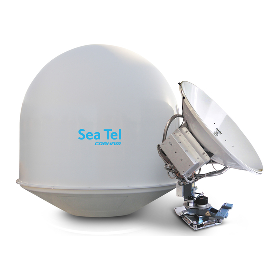
MODEL: 4006-23 IN A 60" RADOME
Look to the Leader. Look to Sea Tel.
Sea Tel Europe
Unit 1, Orion Industrial Centre
Wide Lane, Swaythling
Southampton, UK S0 18 2HJ
Tel: 44 (0)23 80 671155
Fax: 44 (0)23 80 671166
Email: europe@seatel.com
Web:
www.seatel.com
Document. No. 125135
Rev C
Advertisement
Table of Contents
Troubleshooting

Summary of Contents for Sea Tel 4006-23 IN A 60” RADOME
- Page 1 Tel: (925) 798-7979 Southampton, UK S0 18 2HJ Fax: (925) 798-7986 Tel: 44 (0)23 80 671155 Email: seatel@seatel.com Fax: 44 (0)23 80 671166 Look to the Leader. Look to Sea Tel. Web: www.seatel.com Email: europe@seatel.com Web: www.seatel.com July 9, 2007 Document.
- Page 2 All Rights Reserved. The information contained in this document is proprietary to Sea Tel, Inc.. This document may not be reproduced or distributed in any form without the consent of Sea Tel, Inc. The information in this document is subject to change without notice.
- Page 4 Revision History ECO# Date Description February 9, 2006 Initial Production Release, includes FCC TX Mute function information. July 17, 2006 Updated text and drawings 5499 July 9, 2007 Change ACU to DAC-2202. Update text and drawings...
-
Page 5: Table Of Contents
Table of Contents 4006-23 Broadband At Sea 1. INTRODUCTION..........................1-1 1.1. G ..................... 1-1 ENERAL YSTEM ESCRIPTION 1.2. P ............................. 1-1 URPOSE 1.3. S ........................1-1 YSTEM OMPONENTS 1.4. G ....................1-2 ENERAL SCOPE OF THIS MANUAL 1.5. Q ..................... 1-2 UICK VERVIEW OF CONTENTS 2. - Page 6 4006-23 Broadband At Sea Table of Contents 4.4.1. 60” Radome Assembly....................4-2 4.4.2. Antenna Pedestal Mechanical Checks................4-2 4.5. C ........................4-3 ABLE NSTALLATION 4.5.1. Shipboard Cable Installation..................... 4-3 4.5.2. Cable Terminations In The Radome................. 4-3 4.6. B ......................4-4 ELOW ECKS QUIPMENT...
- Page 7 Table of Contents 4006-23 Broadband At Sea 7.2. R ................... 7-2 ECOMMENDED REVENTIVE AINTENANCE 7.2.1. Check ACU Parameters ....................7-2 7.2.2. Latitude/Longitude Auto-Update check ................7-2 7.2.3. Heading Following ......................7-2 7.2.4. Azimuth & Elevation Drive ....................7-2 7.2.5. Test Tracking........................7-2 7.2.6.
- Page 8 4006-23 Broadband At Sea Table of Contents 8.9.3. Satellite Modem....................... 8-4 8.9.4. Router ..........................8-4 8.10. C ............................8-4 ABLES 8.10.1. Antenna Control Cable (Provided from ACU-MUX) ............8-4 8.10.2. Antenna L-Band IF Coax Cables (Customer Furnished)........... 8-4 8.10.3. Multi-conductor Cables (Customer Furnished) ..............8-5 8.10.4.
-
Page 9: Introduction
Introduction 4006-23 Broadband At Sea Introduction WARNING: RF Radiation Hazard - This stabilized antenna system is designed to be used with transmit/receive equipment manufactured by others. Refer to the documentation supplied by the manufacturer which will describe potential hazards, including exposure to RF radiation, associated with the improper use of the transmit/receive equipment. -
Page 10: General Scope Of This Manual
1.4. General scope of this manual This manual describes the Sea Tel Series 03 Antenna (also called the Above Decks Equipment), its’ operation and installation. Refer to the manual provided with your Antenna Control Unit for its’ installation and operating instructions. -
Page 11: Operation
Operation 4006-23 Broadband At Sea Operation Operation of your system is accomplished from the DAC-2200 Antenna Control Unit (ACU). Refer to the operation section of the DAC-2200 Antenna Control Unit manual. 2.1. System Power-up Turn the Power switch on rear panel of the Antenna Control Unit (ACU) ON. 2.2. -
Page 12: Tracking Operation
4006-23 Broadband At Sea Operation 2.5. Tracking Operation Tracking optimizes the antenna pointing, in very fine step increments, to maximize the level of the satellite signal being received. The mode of tracking used in this antenna is a variation of Conical Scanning called DishScan. -
Page 13: Basic System Information
Basic System Information 4006-23 Broadband At Sea Basic System Information This section provides you with some additional information about the satellites you will be using, basics of the your antenna system and other equipment within your system configuration. 3.1. Satellite Basics The satellites are in orbit at an altitude of 22,753.2 Statute Miles positioned directly above the equator. -
Page 14: Signal Level
4006-23 Broadband At Sea Basic System Information to position the antenna where it has an unobstructed view to the desired satellite will restore the antennas ability to receive the satellite signal. Rain Fade - Atmospheric conditions that may cause sufficient loss of signal level include rain, snow, heavy fog and some solar activities such as sun spots and solar flare activity. -
Page 15: Antenna Basics
Basic System Information 4006-23 Broadband At Sea 3.2. Antenna Basics The satellite dish is mounted on a three jointed pedestal. As your boat rolls, pitches and turns in the water, these three joints move to keep the dish pointed at the satellite. The following information is provided to explain some of the basic functions of the antenna: 3.2.1. -
Page 16: Interchangeable Lnbs
& data services. 3.2.6. Stabilization This Sea Tel antenna is stabilized in three axes of motion. Stabilization is the process of de- coupling the ships motion from the antenna. Simply put, this allows the antenna to remain pointed at the satellite while the boat turns, rolls or pitches under it. -
Page 17: Antenna Ade Assembly
Basic System Information 4006-23 Broadband At Sea The System is comprised of two major sections: The Above-Decks Equipment (ADE) is comprised solely of the antenna radome assembly which is mounted outside, on the boats upper deck or mast location. The Below-Decks Equipment (BDE) includes the Antenna Control Unit, satellite modem and all other ancillary equipment that is mounted in various locations throughout the interior of the boat. -
Page 18: Above Decks Ac Power Supply
4006-23 Broadband At Sea Basic System Information choice of positioning commands to point the antenna, search commands to find the satellite signal and tracking functions to maintain optimum pointing. 3.3.3. Above Decks AC Power Supply Pedestal Power - An appropriate source of AC Voltage (110 VAC 60 Hz OR 220 VAC 50 Hz) is required for the above decks equipment. -
Page 19: Installation
Installation 4006-23 Broadband At Sea Installation Your antenna pedestal comes completely assembled in its radome. This section contains instructions for unpacking, final assembly and installation of the equipment. It is highly recommended that installation of the system be performed by trained technicians. 4.1. -
Page 20: Installing The Above-Decks Equipment (Ade)
4006-23 Broadband At Sea Installation 4.4. Installing the Above-Decks Equipment (ADE) 4.4.1. 60” Radome Assembly The antenna pedestal is shipped completely assembled in its 60” radome. WARNING: Hoisting with other than a webbed four-part sling may result in catastrophic crushing of the radome. Refer to the specifications and drawings for the fully assembled weight of your model Antenna/Radome and assure that equipment used to lift/hoist this system is rated accordingly. -
Page 21: Cable Installation
Installation 4006-23 Broadband At Sea 4.5. Cable Installation 4.5.1. Shipboard Cable Installation CAUTION: Rough handling, tight bending, kinking, crushing and other careless handling of the cables and their connectors can cause severe damage. The cables must be routed from the above-decks equipment group through the deck and through various ship spaces to the vicinity of the below-decks equipment group. -
Page 22: Below Decks Equipment
4006-23 Broadband At Sea Installation 4.6. Below Decks Equipment. 4.6.1. System Configuration 4.6.2. Installing the Below Deck Equipment Install the ACU, Terminal Mounting Strip and Multiplexer Panel in your standard 19” Equipment Rack. Connect this equipment as shown in the System Block Diagram. -
Page 23: Ships Gyro Compass Connections
Installation 4006-23 Broadband At Sea • A transmit inhibit output from the ACU will mute the modem transmit when the antenna is mis-pointed 0.5 degrees. This connection is MANDATORY to comply with new FCC Order 04-286 and WRC-03 Resolution 902. 4.6.7. - Page 24 4006-23 Broadband At Sea Installation This Page Intentionally Left Blank...
-
Page 25: Set-Up & Configuration
Contact Sea Tel for the Internet Service Provider (ISP) Network Operation Center (NOC) ASSIGNED IP address, SubNet Mask and the Primary & Secondary DNS addresses if they have not been previously provided to you, or if you have changed providers. -
Page 26: Calibrating Relative Antenna Position (Home Flag Offset)
4006-23 Broadband At Sea Set-up & Configuration Default setting is 0040 and may be incremented, or decremented, to adjust polarization while in Auto-Pol mode. Each increment equals one degree of polarization rotation (0048 = +8 degrees), decrement below 40 for minus polarization (0032 = -8 degrees). Press the UP arrow to increment or the DOWN arrow to decrement the value and then hit the ENTER key to adjust the feed to the new value. -
Page 27: To Calculate Hfo
Set-up & Configuration 4006-23 Broadband At Sea 5.4.1. To Calculate HFO: If Targeting has been optimized by entering a large value of AZ TRIM; First, verify that you are able to repeatably accurately target a desired satellite (within +/- 1.0 degrees). Then you can use the AZ TRIM value to calculate the value of HFO you should use (so you can set AZ TRIM to zero). -
Page 28: To Enter The Hfo Value
4006-23 Broadband At Sea Set-up & Configuration If the antenna went past the bow-line; When you initially target a satellite, the antenna will also go past the satellite position, so that you will have to drive the Azimuth of the antenna DOWN to actually find the satellite. -
Page 29: Radiation Hazard And Blockage Mapping (Az Limit Parameters)
Set-up & Configuration 4006-23 Broadband At Sea enter writing mode and then press the ENTER to save the HFO value in the PCUs NVRAM. You have to drive the antenna CW in azimuth until the home switch is actuated, or re-initialize the antenna to begin using the new HFO value you have entered and saved. - Page 30 RF Radiation Hazard zone(s). When used for “FCC TX Mute” logic output for a single Sea Tel TXRX antenna, this output is used to suppress RF transmissions whenever the antenna is mis-pointed 0.5 degrees or more, is blocked, searching, targeting or unwrapping.
- Page 31 Set-up & Configuration 4006-23 Broadband At Sea EXAMPLE 1 - Three blockage Zones: A ship has a Sea Tel antenna mounted on the port side and an Inmarsat antenna mounted on the starboard side. A mast forward, the Inmarsat antenna to starboard and an engine exhaust stack aft form the three zones where satellite signal is blocked (as shown in the graphic).
-
Page 32: Tx Polarity Setup
4006-23 Broadband At Sea Set-up & Configuration EXAMPLE 3 - One blockage Zone: A ship has a Sea Tel antenna mounted on the center line of the ship. A mast is forward and an engine exhaust stack is aft. In this example the Stack does NOT block the satellite, only the mast forward does. -
Page 33: Default Setup Parameters
Set-up & Configuration 4006-23 Broadband At Sea 5.7. Default Setup Parameters The following table shows the factory default parameters for the DAC-2200, or DAC-2202, Antenna Control Unit interfaced to a Series 06 Antenna PCU. When the installation & setup of your system is finished you can record the “optimized”... -
Page 34: Configuring "Your Lan Computer(S)
4006-23 Broadband At Sea Set-up & Configuration 5.8. Configuring “Your LAN Computer(s)” A computer being used to setup & configure the Series 03 Below Decks Equipment, or one of your Computers installed on the system, must be used to configure some of the system components. The TCP/IP network adapter settings of this computer must be set to obtain IP address automatically. - Page 35 Set-up & Configuration 4006-23 Broadband At Sea Select the ‘Configuration’ tab Scroll down the “The following network components are installed” list and select the ‘TCP/IP’ PC Ethernet LAN card entry item Click the ‘Properties’ box Select the ‘IP Address’ tab, Select the radio button to ‘Obtain an IP address automatically’...
-
Page 36: To Configure Setup Computer With Ms Windows 2000 Operating System
4006-23 Broadband At Sea Set-up & Configuration 5.8.2. To configure Setup Computer with MS Windows 2000 operating system; 1. Click on ‘Start’ 2. Select ‘Settings’ 3. Select ‘Control panel’ 4. Double click on the 'Network and Dial-up Connections' icon 5-12... - Page 37 Set-up & Configuration 4006-23 Broadband At Sea 5. Double click on the 'Local Area Connection' icon 6. Click the ‘Properties’ box 7. Scroll down the Components checked are used by this connection list and select the ‘Internet Protocol (TCP/IP)‘ item 8.
-
Page 38: To Configure Setup Computer With Ms Windows Xp Operating System
4006-23 Broadband At Sea Set-up & Configuration 9. Select the radio button to ‘Obtain an IP address automatically’ 10. Click on ‘OK’. 11. Close all other previously opened dialogue windows. 5.8.3. To configure Setup Computer with MS Windows XP operating system; 1. - Page 39 Set-up & Configuration 4006-23 Broadband At Sea 3. Click on the ‘Network and Internet Connections’ icon 4. Click on the ‘Network Connections’ icon in the bottom portion of the screen 5. Double click on the ‘Local Area Connection’ icon 5-15...
- Page 40 4006-23 Broadband At Sea Set-up & Configuration 6. Click the ‘Properties’ box 7. Scroll down the This connection uses the following items list and select the ‘Internet Protocol (TCP/IP)‘ item 8. Click the ‘Properties’ box 9. Select the radio button to ‘Obtain an IP address automatically’...
-
Page 41: Functional Testing
6.1. ACU / Antenna System Check 1. Press RESET on the ACU front panel to initialize the system. Verify the display shows "SEA TEL INC - MASTER" and the ACU software version number. Wait 10 seconds for the display to change to "SEA TEL INC - REMOTE"... -
Page 42: Four Quadrant Tracking Test
0.5 Amp. This logic output control signal is used for: • When used as simple “BLOCKED” logic output for a single Sea Tel antenna, this output could be used to light a remote LED and/or sound a buzzer to alert someone that the antenna is blocked, and signal is lost. -
Page 43: Test Broadband Operation
Functional Testing 4006-23 Broadband At Sea SW2 terminal of the Terminal Mounting Strip. If your satellite modem requires an open to “Mute”, refer to SYSTEM TYPE parameter 16 value to reverse the output logic from the ACU. To Test the blockage function: 1. - Page 44 4006-23 Broadband At Sea Functional Testing This Page Intentionally Left Blank...
-
Page 45: Maintenance And Troubleshooting
7.1. Warranty Information Sea Tel Inc. supports this system with a ONE YEAR warranty on Labor and TWO YEARS warranty on parts. What’s Covered by the Limited Warranty? The Sea Tel Limited Warranty is applicable for parts and labor coverage to the complete antenna system, including all above-decks equipment (radome, pedestal, antenna, motors, electronics, wiring, etc.) and... -
Page 46: Recommended Preventive Maintenance
4006-23 Broadband At Sea Maintenance and Troubleshooting Should technical assistance be required to repair your system, the first contact should be to the agent/dealer that you purchased the equipment from. Please refer to the complete warranty information included with your system. 7.2. -
Page 47: Mechanical Checks
Maintenance and Troubleshooting 4006-23 Broadband At Sea 7.2.7. Mechanical Checks Turn the pedestal power supply OFF 1. Inspect inside of radome for signs that the dish or feed have been rubbing against the inside of the fiberglass radome. 2. Rotate the pedestal through its full range of azimuth motion. The antenna should rotate freely and easily with light finger pressure. -
Page 48: Series 06 Txrx Antenna Initialization
4006-23 Broadband At Sea Maintenance and Troubleshooting Less DC Servo Motors in torque mode. The Torque acting on the mass of the antenna cause it to move, restoring the rate sensors to their original position, and closing the control loop. Since the rate sensors only monitor motion and not absolute position, a second input is required in each axis as a long term reference to keep the antenna from slowly drifting in position. -
Page 49: Reference Sensor Testing
Maintenance and Troubleshooting 4006-23 Broadband At Sea is -0.005 degrees, the Level error is + 0.005 degrees and the Azimuth error is -0.016 degrees. The normal range of these numbers is FFF0 to 000F and they typically will bounce around randomly within this range. -
Page 50: Open Loop Motor Test
4006-23 Broadband At Sea Maintenance and Troubleshooting 7.3.6. Open Loop Motor Test The ACU provides a means for driving each individual torque motor to test that motors functionality. By driving each axis and observing the resulting motion of the antenna, a coarse operational status of the motor and motor driver can be established. -
Page 51: To Read/Decode An Acu Error Code 0008 (Pedestal Error)
Maintenance and Troubleshooting 4006-23 Broadband At Sea To view, or change, the Satellite Reference Mode status, select the SAT REF remote parameter: 1. Press the RIGHT arrow, then press the UP arrow and last press the ENTER key to turn Satellite Reference Mode ON. -
Page 52: Get Remote Gps Lat/Lon Position
S (North or South), LON will be followed by E or W (East or West), then a status character and finally a checksum character. Furuno default value is in Japan at 34.4N 135.2E (@3444,N,13521,E,,_). After acquiring a good fix at Sea Tel the string is @3800,N,12202,W,A^ for our 38N 122W Latitude and Longitude position. -
Page 53: Vdc Polang Alignment
Maintenance and Troubleshooting 4006-23 Broadband At Sea The recommend balancing order is Elevation Axis with the antenna pointed at the horizon (referred to as front to back balance). Elevation Axis with the antenna pointed at zenith (referred to as top to bottom balance). Then Cross Level axis at any elevation position (referred to as side to side balance). -
Page 54: To Reset/Reinitialize The Antenna
4006-23 Broadband At Sea Maintenance and Troubleshooting 6. Press ENTER to step the menu to REMOTE PARAMETERS. 7. Press the LEFT arrow key and then press the ENTER key to save the settings in the PCU. This saves the new tilt bias settings in the PCU. Reset or re-initialize the antenna to verify that the Level cage is properly level with the new settings. -
Page 55: Antenna Stowing Procedure
The normal operating condition for the Sea Tel Antenna system is to remain powered up at all times. This ensures that the antenna remains actively stabilized to prevent physical damage to the antenna pedestal and reduce condensation and moisture in the radome to prevent corrosion. - Page 56 4006-23 Broadband At Sea Maintenance and Troubleshooting This Page Intentionally Left Blank 7-12...
-
Page 57: Technical Specifications
Withstand relative average winds up to 100 MPH from any direction. Ingress Protection Rating All Sea Tel radomes have an IP rating of 56 *NOTE: Radome panels can absorb up to 50% moisture by weight. Soaked panels will also have higher attenuation. -
Page 58: Stabilized Antenna Pedestal Assembly
4006-23 Broadband At Sea 4006-23 Technical Specifications 8.4. Stabilized Antenna Pedestal Assembly Type: Three-axis (Level, Cross Level, AZ) Stabilization: Torque Mode Servo Stab Accuracy: 0.3 degrees MAX, 0.15 degrees RMS in presence of specified ship motions (see section 1.8). LV, CL, AZ motors: Size 23 Brushless DC Servo. -
Page 59: Unlimited Azimuth Modem/Multiplexer (3 Channel)
4006-23 Technical Specifications 4006-23 Broadband At Sea 8.6. Unlimited Azimuth Modem/Multiplexer (3 Channel) Combined Signals 950-2050 MHz RX IF and Pedestal M&C. Connectors: RX IF F female Rotary Joint SMA female DC / Ped M&C 9 pin D-Sub Connector Pedestal M&C Modulation Mode Full Duplex... -
Page 60: Below Decks Equipment
DE-9P 8.10.2. Antenna L-Band IF Coax Cables (Customer Furnished) Due to the loss across the length of the RF coaxes at L-Band, Sea Tel recommends the following coax cable types (and their equivalent conductor size) for our standard pedestal installations:... - Page 61 4006-23 Broadband At Sea 8.10.3. Multi-conductor Cables (Customer Furnished) Due to the voltage loss across the multi-conductor cables, Sea Tel recommends the following wire gauge for the AC & DC multi-conductor cables used in our standard pedestal installations: Run Length...
- Page 62 4006-23 Broadband At Sea 4006-23 Technical Specifications This Page Intentionally Left Blank...
- Page 63 DRAWINGS 4006-23 Broadband At Sea DRAWINGS The drawings listed below are provided as apart of this manual for use as a diagnostic reference. 9.1. 4006-23 Ku-Band Model Specific Drawings Drawing Title 125134-1_D 4006-23 System, w/60” Radome 124708-1_H 4006-23 System Block Diagram 124706-1_H 4006-23 General Assembly 123511_A...
- Page 64 4006-23 Broadband At Sea DRAWINGS This Page Intentionally Left Blank...
- Page 65 SINGLE LEVEL MFG BILL OF MATERIAL FIND PART NO DESCRIPTION REFERENCE DESIGNATOR 124706-1 GENERAL ASS'Y, 4006-23 123628-1 RADOME ASS'Y, 4003/4006 GA INSTALL, 6 (SEE SALES ORDER) 124167-4 SSPB, KU-BAND, CODAN LBUC, 8W, 48VD (SEE SALES ORDER) 122188-3 LNB, 10.95 TO 11.70 GHz, PLL, +/- 3 ppm, T (SEE SALES ORDER) 122188-2 LNB, 12.25 TO 12.75 GHz, PLL, +/- 3 ppm, T...
- Page 67 SINGLE LEVEL MFG BILL OF MATERIAL FIND PART NO DESCRIPTION REFERENCE DESIGNATOR 124706-1 GENERAL ASS'Y, 4006-23 125622-1 RADOME ASS'Y, 4003/4006 GA INSTALL, 5 123329-1 FEED ASS'Y, KU, CROSS-POLAR, W/ROTA 122188-1 LNB, 11.70 TO 12.20 GHz, PLL, +/- 3 ppm, T 122188-2 LNB, 12.25 TO 12.75 GHz, PLL, +/- 3 ppm, T 122188-3...
- Page 68 SINGLE LEVEL MFG BILL OF MATERIAL FIND PART NO DESCRIPTION REFERENCE DESIGNATOR 117429-1 WAVEGUIDE, WR-75, 180 DEG E-BEND, 1.2 117858 WAVEGUIDE FILTER, WR-75, KU-BAND, TX 114280-5 WAVEGUIDE, WR-75, 90 DEG H-BEND, 1.5x 123755-1 WAVEGUIDE, WR-75, RIGID, W/FLEX 123755-1 WAVEGUIDE, WR-75, RIGID, W/FLEX 115477-6 WAVEGUIDE, WR-75, ROTARY JOINT, L-ST 125411-2...
- Page 70 SINGLE LEVEL MFG BILL OF MATERIAL FIND PART NO DESCRIPTION REFERENCE DESIGNATOR 123508-3 PEDESTAL ASS'Y, 4006 126573-1 ELECT.EQU.FRAME ASS'Y, 4006R-23 KU-B 124400 WEIGHT CONFIGURATION, 4006 123511-1 ANTENNA ASS'Y, 4006 115998-2 STRAP, RIGID WAVEGUIDE, KU-BAND 124393 BRACKET, RIGID WAVEGUIDE (NOT SHOWN) 114972-3 CABLE ASS'Y, SMA(M) - SMA(M), 84 IN (NOT SHOWN)
- Page 71 SINGLE LEVEL MFG BILL OF MATERIAL FIND PART NO DESCRIPTION REFERENCE DESIGNATOR 114593-162 SCREW, SOCKET HD, 10-32 x 3/8, S.S. 114593-168 SCREW, SOCKET HD, 10-32 x 7/8, S.S. 114580-009 WASHER, FLAT, #8, S.S. (NOT SHOWN) 121655-1 LABELS INSTALLATION GENERAL ASS'Y, 4006-23 PROD FAMILY EFF.
- Page 72 REVISION HISTORY NOTES: UNLESS OTHERWISE SPECIFIED ECO# DESCRIPTION DATE 1. APPLY ADHESIVE PER SEATEL SPEC. 121730. REFERENCE DRAWINGS: 2. TORQUE THREADED FASTENERS PER 5200 VIEWS CHANGED TO MATCH BASE SPINDLE ASS'Y 6-13-06 SEATEL SPEC. 122305. 124708 SYSTEM BLOCK DIAGRAM. DELETED TRIM WEIGHTS, ITEMS 17, 18 & 19 FROM BOM 5220 6-20-06 3.
- Page 73 SINGLE LEVEL MFG BILL OF MATERIAL FIND PART NO DESCRIPTION REFERENCE DESIGNATOR 122092 REFLECTOR MACHINING, 40 IN 123329-1 FEED ASS'Y, KU, CROSS-POLAR, W/ROTA 122034-1 CLIP, 40 IN. REFLECTOR 122034-2 CLIP, 40 IN. REFLECTOR 122066 VERTEX FEED, 40 IN., 4003 MOD. 114588-829 SCREW, PAN HD, PHIL, 10-32 x 1/2, S.S.
- Page 74 REVISION HISTORY NOTES: UNLESS OTHERWISE SPECIFIED ECO# DESCRIPTION 1. APPLY ADHESIVE PER SEATEL SPEC. 121730. DATE TORQUE THREADED FASTENERS PER 10-28-05 PRODUCTION RELEASE FROM X4 TO A. SEATEL SPEC. 122305. 4X STUD SHALL NOT PROTRUDE BEYOND THIS SURFACE SECTION A-A 50 8X SCALE 1 : 2 45°...
- Page 76 SINGLE LEVEL MFG BILL OF MATERIAL FIND PART NO DESCRIPTION REFERENCE DESIGNATOR 122874-2 RADOME TOP, 60 IN W/ LIP, ZERO DRAFT, 123126 RADOME BASE FAB ASS'Y, 60 IN, W/ LIP, 109258-8 STRAIN RELIEF, W/SEALING LOCK NUT 118576 MOUNTING KIT, PEDESTAL 119801-012 CABLE TIE, NYLON, 4 INCH 119801-019...
- Page 80 SINGLE LEVEL MFG BILL OF MATERIAL FIND PART NO DESCRIPTION REFERENCE DESIGNATOR 125096-1 BELT KIT, 4006 123845-1 PCU ENCLOSURE ASS'Y, 4006 116024-5 SHIELDED POLANG RELAY ASS'Y 122937-1 LEVEL CAGE ASS'Y, BOTTOM EXIT, 90 DE 116139-3 SIZE 23 BRUSHLESS MOTOR 114079-2 PULLEY, 1/5P 10T, 2FLG 114590-142 SCREW, SOCKET SET-CUP, 6-32 x 1/8, S.S.
- Page 81 SINGLE LEVEL MFG BILL OF MATERIAL FIND PART NO DESCRIPTION REFERENCE DESIGNATOR 125093-1 SPARE PARTS KIT, 4006 STANDARD 117168-1 MODEM ASS'Y, PEDESTAL, 3-CH. 75 OHM 117168-2 MODEM ASS'Y, BASE, 3-CH. 75 OHM 122555-90 POWER SUPPLY, IDEC, PS5R-SE24 114789-810 TRANSPORT CONTAINER SPARE PARTS KIT, 4006 PREMIUM PROD FAMILY EFF.
- Page 82 SINGLE LEVEL MFG BILL OF MATERIAL FIND PART NO DESCRIPTION REFERENCE DESIGNATOR 125094-1 SPARE PARTS KIT, 4006 PREMIUM 122188-1 LNB, 11.70 TO 12.20 GHz, PLL, +/- 3 ppm, T 122188-2 LNB, 12.25 TO 12.75 GHz, PLL, +/- 3 ppm, T 122188-3 LNB, 10.95 TO 11.70 GHz, PLL, +/- 3 ppm, T 124068-1...
- Page 84 SINGLE LEVEL MFG BILL OF MATERIAL FIND PART NO DESCRIPTION REFERENCE DESIGNATOR 112657 MACHINING, TERMINAL MOUNTING STRIP 116529 PCB ASS'Y, TERMINAL MOUNTING, 25 PIN 112936 CABLE ASS'Y, D-SUB, 25 PIN 116527 PCB ASS'Y, TERMINAL MOUNTING, 9 PIN 116669-36 CABLE ASS'Y, D-SUB, 9-PIN, 36 IN. 121228-3072 STANDOFF, HEX, F/F, 6-32 X .25 OD X .50, 114588-146...
- Page 86 SINGLE LEVEL MFG BILL OF MATERIAL FIND PART NO DESCRIPTION REFERENCE DESIGNATOR 116880 PANEL MACHINING, RACK, BASE MUX 117168-2 MODEM ASS'Y, BASE, 3-CH. 75 OHM 117611-4 MODEM ASS'Y, BASE, 3 CH. -200, 50 OHM 116388 BRACKET, CONNECTOR 115492-1 ADAPTER, N(F)-SMA(F), W/FLANGE 110567-19 ADAPTER, N(F)-N(F), STRAIGHT, FLANGE 114972-9...