
Subscribe to Our Youtube Channel
Related Manuals for Epiphone Plexi SE PCB


Summary of Contents for Epiphone Plexi SE PCB
- Page 1 Plexi SE PCB Valve Junior Conversion Build Manual Plexi SE PCB Valve Junior Conversion Version 2 Build Manual 23 August 2009 1 of 34...
-
Page 2: Introduction
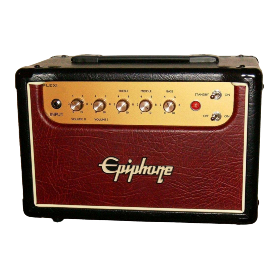
This manual contains instructions to convert an Epiphone Valve Junior into a 5 watt single ended tube amplifier modeled after the legendary Marshall 1959 Super Lead (Plexi). The heart of the amp is the Plexi SE PCB, which conveniently lays out the circuit in a printed circuit board, PCB, package. -
Page 3: Electrical Shock Warning
GuitarAmplifierPCBs.com reserves the right to make design changes or improvements without obligation to revise prior versions. All specifications are subject to change without notice. Plexi SE PCB Valve Junior Conversion Version 2 Build Manual 23 August 2009... -
Page 4: Table Of Contents
Remove the Stock EVJ Circuit Board..............9 Prepare the Chassis ......................11 Layout and Drill ......................11 6.1.1 Layout the Plexi SE PCB for Drilling ..............11 6.1.2 Layout the Faceplate for drilling ................12 6.1.3 Drilling the Chassis....................13 Plexi SE PCB ........................ -
Page 5: Project Overview
4.1 Here’s what you’ll need: 4.1.1 Parts: • The Plexi SE PCB • Misc. parts and components (refer to the Plexi SE PCB parts list document for a full listing of what parts are needed and where you can buy them) 4.1.2 Tools:... -
Page 6: Let's Get Started
Remove the four chassis screws and pull out the chassis. Plexi SE PCB Valve Junior Conversion Version 2 Build Manual 23 August 2009 6 of 34... -
Page 7: Remove The Evj's Stock Components
So, the output transformer needs to be unscrewed from the chassis and pushed aside. Plexi SE PCB Valve Junior Conversion Version 2 Build Manual 23 August 2009 7 of 34... -
Page 8: Clean Up The Power Transformer
These need to be pulled outside and secured as well. After the leads are all pulled outside the chassis, bundle them together and tie them off. Plexi SE PCB Valve Junior Conversion Version 2 Build Manual 23 August 2009 8 of 34... -
Page 9: Remove The Volume Potentiometer
Lift the ground wire from the star ground post. Unplug the input jack wire at the circuit board. Remove the six (6) screws fastening the circuit board to the chassis. Plexi SE PCB Valve Junior Conversion Version 2 Build Manual 23 August 2009 9 of 34... - Page 10 Salvage the ground wire from the stock circuit board for use later. Unscrew the input jack and remove it from the chassis. Set it aside for use later. Plexi SE PCB Valve Junior Conversion Version 2 Build Manual 23 August 2009 10 of 34...
-
Page 11: Prepare The Chassis
6.1.1 Layout the Plexi SE PCB for Drilling Since the Plexi SE PCB was designed to use the stock EVJ chassis standoffs, the best method to mark the additional chassis holes is to install the board. Lay the circuit board in the chassis, align the stock mounting studs, and install two to three screws to fasten the board. -
Page 12: Layout The Faceplate For Drilling
Affix the plan to the chassis with a generous amount of white glue or tape. Note: This is not a picture of the Plexi SE PCB drill plan. Instead, it is a drill plan of a similar build. But it adequately represents the front panel of the Plexi SE PCB. -
Page 13: Drilling The Chassis
Deburr or countersink each hole to ensure no sharp edges will cause injury or component failure. 7. Plexi SE PCB 7.1 Assemble the Plexi SE PCB The anticipation has been killing you, hasn’t it? Finally, the assembly of the Plexi SE PCB begins. -
Page 14: Pcb Standoffs
Position the notch in this socket so that it is pointing toward the two noval sockets. Solder them into the board. Plexi SE PCB Valve Junior Conversion Version 2 Build Manual 23 August 2009 14 of 34... -
Page 15: Spade Connectors
Instead of using spade connectors, the wire leads should be soldered directly to the board in location marked above. Don’t worry about this now. It will be cover later when the board is installed in the chassis. Plexi SE PCB Valve Junior Conversion Version 2 Build Manual... -
Page 16: Diodes
Solder them to the board. Trim the leads off at the top of each solder pool, like this. Plexi SE PCB Valve Junior Conversion Version 2 Build Manual 23 August 2009... -
Page 17: The "Plexi Preamp
7.1.5 The “Plexi Preamp” To configure the Plexi SE PCB to have a 1959 Super Lead “Plexi” preamp, install the various components as shown in the picture below. Determine the component value from the schematic and/or chassis layout drawing. -
Page 18: The "Cascade Preamp
7.1.6 The “Cascade Preamp” To configure the Plexi SE PCB to have a Cascade (or JCM800) preamp, install the various components as shown in the picture below. Determine the component value from the schematic and/or chassis layout drawing. Notice how the leads of the 470K resistor and 250pF capacitor are inserted in the Cascade solder pad locations. -
Page 19: Wiring The Heaters
7.1.7 Wiring the Heaters Cut two 12” lengths of wire and twist them together as shown. Cut this twisted pair in half. Plexi SE PCB Valve Junior Conversion Version 2 Build Manual 23 August 2009 19 of 34... - Page 20 Twist the wires together as shown. Strip ¼” of the insulation off of the ends of the wires. Insert the leads into the solder pad locations on the middle tube socket labeled “HTR” for heaters. Plexi SE PCB Valve Junior Conversion Version 2 Build Manual...
-
Page 21: Filter Capacitors
(the longer one) into the square pad and the negative lead (as indicated by the downward arrow and “-“ symbol) in the round pad. Solder and trim the leads. Plexi SE PCB Valve Junior Conversion Version 2 Build Manual 23 August 2009... -
Page 22: Bypass Capacitors
Not all of the components will look like what’s called for in the current parts list. The bypass capacitors have changed since the construction of this documentation build. Plexi SE PCB Valve Junior Conversion Version 2 Build Manual 23 August 2009... -
Page 23: Install The Remaining Components
Install, solder and trim all of the remaining components in the circuit. Refer to the latest version of the schematic or chassis layout drawing on GuitarAmplifierPCBs.com, the Plexi SE PCB, and/or the component package to identify, locate and position component values. -
Page 24: Input Jack
Insert the white lead into the “IN” pad and the black lead into a ground pad. Solder and trim. The input section is done. Plexi SE PCB Valve Junior Conversion Version 2 Build Manual 23 August 2009 24 of 34... -
Page 25: Control Leads
All of the solder joints should be shiny. It’s now ready to be installed in the chassis. Plexi SE PCB Valve Junior Conversion Version 2 Build Manual 23 August 2009... -
Page 26: Putting It All Together
8.1 Install the New Components Now that everything is out of the chassis that we don’t need, the chassis has been drilled, and the Plexi SE PCB has been assembled, we can prep the chassis and install all of the new components. - Page 27 Refer to the schematic and layout diagram for additional information regarding the wiring hookup locations. It should look like the picture above when you’re done. Plexi SE PCB Valve Junior Conversion Version 2 Build Manual 23 August 2009...
- Page 28 Inspect the board for any solder that may have splashed during this procedure. Fasten the ground wires from the Plexi SE PCB and the output transformer to the star ground screw post. Good Job! You’re almost done. But, before you start celebrating, you still have to review your work, start it up and test the voltages.
-
Page 29: Turn On The Power
The fuse should be rated for 2A Slo-Blo. • Check that the heater element supply (orange wires) is equipped with a good fuse. The fuse should be rated for no more than 4A Slo-Blo. Plexi SE PCB Valve Junior Conversion Version 2 Build Manual... -
Page 30: Power Up Without Tubes
If a significant deviation from these readings is observed, turn off the amp, unplug the mains power and investigate. These measurements will read high since there is no load on the transformer. Plexi SE PCB Valve Junior Conversion Version 2 Build Manual... - Page 31 A slight fluctuation is normal. If a difference greater than 5-10 Vdc is measured, something is drawing current when it shouldn’t. Turn off the amp and troubleshoot the problem. Turn OFF the amplifier. Plexi SE PCB Valve Junior Conversion Version 2 Build Manual 23 August 2009...
-
Page 32: Power Up With Tubes
Switch the amp’s power switch to the “ON” position. With your voltmeter, check the following voltages. If a significant deviation from these readings is observed, turn off the amp, unplug the mains power and investigate. Plexi SE PCB Valve Junior Conversion Version 2 Build Manual... - Page 33 Plexi SE PCB Valve Junior Conversion Version 2 Build Manual 23 August 2009 33 of 34...
-
Page 34: Finish Things Up
Press them in until they are flush with the cabinet surface. Attach the back panel with the stock screws. Congratulations! Your have successfully converted your Epiphone Valve Junior into a Plexi SE. Plug in a guitar and enjoy your new amp.
Need help?
Do you have a question about the Plexi SE PCB and is the answer not in the manual?
Questions and answers