Table of Contents
Troubleshooting

Related Manuals for Shinko Electric CHC-S1245-5

Summary of Contents for Shinko Electric CHC-S1245-5
- Page 1 Digital Photo Printer CHC-S1245-5 Maintenance Specifications Date: March 8, 2005 Revised: Revision: First Edition Confirmation Signature Customer Shinko Electric Co., Ltd. Approved Inspected Drew Shinko Electric Co., Ltd. YQE8-J0092E...
- Page 2 Revision Record Revised Date Correction Descriptions ECN No. symbol - 3/8/2005 First Edition YQE8-J0092E...
-
Page 3: Table Of Contents
Contents 1 Scope ..............................1 2 Periodic Inspection..........................2 2.1 Parts Required..............................2 2.2 Tools Required ..............................2 2.3 Tool Required ..............................2 2.4 Maintenance Schedule ............................. 3 2.5 Inspection Contents ............................4 2.6 Description for point of cleaning ........................6 2.7 Description for point of lubrication ....................... 11 3 Adjustment ............................14 3.1 Power Unit Voltage Setting ........................... -
Page 4: Scope
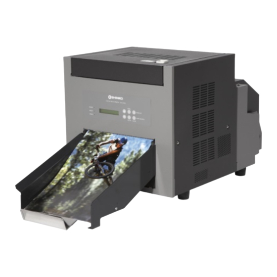
1 Scope This document is applicable to the following Shinko Digital Photo Printer. Applicable Model Name:CHC-S1245-5 Related Documents ・Maintenance Parts Replacement Procedures YQE8-J0093E ・Operation Manual YTE8-J0124E YQE8-J0092E... -
Page 5: Periodic Inspection
2 Periodic Inspection 2.1 Parts Required № Description Parts Number Q’ty Supplier Remarks 1 1 Head Cleaning Kit 060-91-7146 Option 2 Isopropyl Alcohol (IPA) or Ethyl Some Available on Alcohol (more than 99% purity) market 3 Bleached Cloth Some Available on market 4 Grease (equivalent to MOLYKOTE Some Available on... -
Page 6: Maintenance Schedule
2.4 Maintenance Schedule Periodic inspection is performed according to the following schedule. If problem is detected during the inspection, adjustment or Replacement of parts may be necessary. ○(circle) denotes to Perform, R denotes to Replace Schedule № Inspect Item Remarks Number of Prints (K=1,000 prints) 100K... -
Page 7: Inspection Contents
2.5 Inspection Contents № Inspection Items Inspection Contents 1 Thermal Head Perform test printing, and replace the Thermal Head ASSY if the following problem occurs (Refer to Section 4 of this document for test printing procedures) - Visible white line on output surface (ink does not transfer to the paper even after cleaning the thermal print head. - Page 8 № Inspection Item Inspection Contents Apply some grease (Molykote PG-671) to each of the following Lubricate sections. (1)DC Motor ASSY (Ribbon roll-up) ①Circumference of Worm Gear (2)DC Motor (Pinch Roller) ①Circumference of Worm Gear ②Circumference of the Pinch Cam (left and right) ③Circumference of Gear (3)DC Motor (Thermal Head) ①Circumference of Worm Gear...
-
Page 9: Description For Point Of Cleaning
Description for point of cleaning (1)Covers for remove Upper Cover Side Cover L2 Side Cover L Front Cover Side Cover R2 Side Cover R (2)Thermal Head Heat Element Cleaning while opening Upper Unit Thermal Head Heat Element (3)Platen Cleaning while opening Upper Unit Platen YQE8-J0092E... - Page 10 (4)Cleaning Roller Paper Ejection side Remove the Cleaning Roller and clean while opening Upper Unit Cleaning Roller Paper Ejection side (5)Cleaning Roller Paper Feed side Remove the Cleaning Roller and clean while opening Upper Unit Cleaning Roller Paper Feed side (6)Paper Feed Roller Clean the Paper Feed Roller while opening Paper Cover.
- Page 11 (7)Paper Feed Roller (For Paper Transport) Remove Cleaning Roller Paper Feed side Remove 2 screws (M3 x 6) which hold Print Position Sensor Cover, and remove Print Position Sensor Cover. Print Position Sensor Cover Screw Remove side cover R. Remove a screw (M3 x 6) which holds Feed Pinch Up Lever and remove Feed Pinch Up Lever. Feed Pinch Up Lever Screw Remove the spring (roller side) which holds Feed Pinch Roller, move the Feed Pinch Roller upwards, and...
- Page 12 (8)Cleaning Ejection Roller Remove Side Cover L, Side Cover R, Front Cover, and cleaning roller (ejection side). Remove 2 screws (M3x6) which hold PCB HSSV7-LCDSOSA-F ASSY and remove the PCB (removing wire harness is not required). Warning: Do not touch the blade of the cutter unit in order to avoid injury. HSSV7-LCDSOSA-F ASSY Screw Remove 2 screws (M3x6) which hold the Paper Cutter Unit, then remove the Paper Cutter Unit, and clean...
- Page 13 (10)Paper Edge Sensor and Ribbon Sensor Clean the Paper Edge Sensor and Ribbon Sensor with the upper unit opened. Paper Edge Sensor Ribbon Sensor (11)Main Pinch Roller Clean the Main Pinch Roller with the upper unit opened. Main Pinch Roller YQE8-J0092E...
-
Page 14: Description For Point Of Lubrication
2.7 Description for point of lubrication (1)Lubricating driving system of DC motor for ribbon winding Lubricate the driving system of DC motor for ribbon winding with Side Cover L removed. Worm Gear (2)Lubricating driving system of DC motor for pinch roller Lubricate the driving system of DC motor for pinch roller with Side Cover L and Side Cover R removed. - Page 15 (3)Lubricating driving system of DC motor for thermal head Lubricate the driving system of DC motor for thermal head with the Upper Cover and Head Gear Cover removed. Worm Gear Circumference of Head Cam Circumference of Head Cam (4)Lubricating DC motor system for paper feed pinch roller Lubricate the DC motor system for paper feed pinch roller with Side Cover L and Side Cover L2 removed.
- Page 16 (5)Lubricating DC motor system for ejection pinch roller Lubricate the DC motor system for ejection pinch roller with Side Cover R removed. Worm Gear (6)Lubricating driving system of sub-motor Lubricate the driving system of sub-motor with Side Cover L and Side Cover L2 removed. Circumference of Pinion Gear YQE8-J0092E...
-
Page 17: Adjustment
3 Adjustment 3.1 Power Unit Voltage Setting Remove the main cover and set the power unit voltage by the following procedures. 3.1.1 +5V Setting (1) Measurement Conditions Turn the Power on, and measure under ready condition. (Ink Ribbon and Paper are not required with control PC board connected) (2) Setting Voltage Connect the digital voltmeter directly to the +5V terminal (pin 1 or 2) and 0V terminal (pin 3 or 4) of CN3 connector on DC Power Supply and verify whether Power output is under the following figure. -
Page 18: Thermal Head Power (Thv) Setting
3.1.2 Thermal Head Power (THV) Setting (1) Measurement Conditions Turn the Power on, and measure under ready condition. (Ink Ribbon and Paper are not required with control PC board connected) (2) Setting Voltage Open the Upper Cover, and read the THV value that is stated in the nameplate on the Thermal Head cover (see below). -
Page 19: Timing Belts Adjustment
3.2 Timing Belts Adjustment 3.2.1 For Feed Roller Drive Loosen Tension Pulley Screw. Tension pulley presses timing belt at appropriate strength by spring. Tighten Tension Pulley Screw. Timing Belts Tension Pulley Screw 3.2.2 For Feed Roller Drive Loosen Tension Pulley Screw. Tension pulley presses timing belt at appropriate strength by spring. -
Page 20: Print Density Adjustment
Print Density Adjustment Print density setting is done for every Thermal Head. Therefore after replacing the thermal head, set the print density by the following procedures. Turn the Power On by pressing “PAPER SET” and “CLEAR/PAPER REWIND” keys at the same time. LCD displays “Density Setup Mode”... -
Page 21: Resetting Maintenance Print Counter And Cutter Counter
3.4 Resetting Maintenance Print Counter and Cutter Counter Reset the Maintenance Print Counter after replacing Thermal Head, and reset the cutter counter after Paper Cutter Unit. Turn the power on while pressing “-“ and “MENU” keys. LCD displays “Maintenance” and “Ready” afterwards. Initializing Maintenance READY:8×10... - Page 22 (Continued from the previous page) Cut Counter If you are resetting Cut Counter, press “ENTER” key here. **** Press “ENTER” key. RESET? If you are resetting, press “ENTER” key. Otherwise, press “CLEAR” key. Print2 0 Press “CLEAR” key and escape from Cut Counter menu.
-
Page 23: Test Printing
4 Test Printing After adjustment and/or parts replacement, go to test print and verify the printer works properly. The contents of self-diagnostic by test prints. Print mechanism Thermal Head Total test of DC Power Supply and Mechanic Control Boards. If there are any troubles in test print, Re-confirm adjustment and/or replacement procedures. If the problem still exists after re-confirmation, go to Troubleshooting to take corrective action. -
Page 24: Troubleshooting
5 Troubleshooting 5.1 How to Use This Specification This document describes each of the trouble conditions that may occur. The following is the explanation to the Symptom and Check Item. Symptom Check Item A-B-C-D No power when the power switch is turned to ON (I) position. -
Page 25: Troubleshooting Table
5.2 Troubleshooting Table 5.2.1 Troubles during Power On and Off Symptom Check Item No power when the power switch is turned on to (I) Position. A C B E (After verification that POWER LED at operation panel does not light and no LCD messages. - Page 26 Check Probable Cause Corrective Action Item Verify that power cord is properly connected to the power AC Power Cord connection plug. Also make sure that power cord is properly connected to the inlet plug on the device side. Use digital voltmeter or tester to verify that each DC Output value is correct.
-
Page 27: Error Messages On Lcd Display When Power Is On
5.2.2 Error Messages on LCD Display when Power Is On Symptom Check Item Control Error Mecha Error 01 Mecha Error 02 E F D N A Mecha Error 03 Mecha Error 04 Mecha Error 05 B C D N A Mecha Error 06 Mecha Error 07 Mecha Error 08 I D N A... - Page 28 Check Probable Cause Corrective Action Item Replace PCB HSSV7-CONT-F ASSY 1 and if replaced HSSV7-CONT-F ASSY part works, the original part is defective. defective. Verify that the cable between DC Motor ASSY(Pinch Roller Up/Down) and PCB HSSV7-CONT-F ASSY (CN12-CN62) Defective on DC Motor ASSY (Pinch is properly connected.
- Page 29 Verify that the cable between Ribbon Sensor ASSY and PCB HSSV7-JUNCTION-F ASSY (CN53-CN87, CN53-CN88) is Defective on Ribbon Sensor ASSY, its properly connected. connector, or cable disconnection. Replace Ribbon Sensor ASSY 27 and if it works, the original part is defective. Verify that the cable between Pinch Roller Position sensor and PCB HSSV7-JUNCTION-F ASSY (CN48-CN80, CN48-CN81) is properly connected.
- Page 30 Verify that the cable between Paper Edge Sensor and PCB HSSV7-JUNCTION-F ASSY (CN45-CN82) is properly connected. If it is abnormal, repairing at manufacturer is Defective Paper Edge Sensor, its required. connector or disconnection. Replace PCB HSSV7-SEN2-F ASSY 24 and if it works, the original part is defective.
- Page 31 Verify that the cable between Ejection Pinch Roller Position sensor and PCB HSSV7-JUNCTION-F ASSY (CN39-CN84, Defective Ejection Pinch Roller CN39-CN85) is properly connected. If it is abnormal, Position sensor, its connector, or cable repairing at manufacturer is required. Verify that the cable between DC Motor ASSY (Ejection disconnection.
-
Page 32: Troubles In Operation Buttons And Indicators
5.2.3 Troubles in Operation Buttons and Indicators Symptom Check Item LED lights on Operation Panel do not display or are constantly displayed. A C D E A C D E LCD does not display properly. A B D Operation Buttons do not operate. YQE8-J0092E... - Page 33 Check Probable Cause Corrective Action Item Verify that cable connection between Operation panel and Operation Panel connector is defective PCB HSSV7-CONT-F ASSY (CN13-CN21) is properly or disconnected. connected. If it is abnormal, repairing at manufacturer is required. Replace HSSV7-LCDSOSA-F ASSY 2 and if the replaced Operation Switch is defective.
-
Page 34: Troubles In Paper Feed
5.2.4 Troubles in Paper Feed Symptom Check Item A B C D E N Cannot initially load the paper. Paper Empty is displayed. F O D H Paper does not properly eject after printing. Scratches on the surface of the paper. Front part of paper is bent. - Page 35 Check Probable Cause Corrective Action Item Verify that the part inside the Paper Box is properly working. Defective part inside Paper Box. If it is abnormal, repairing at manufacturer is required. Replace DC Motor ASSY (Paper Feed Pinch Up/Down) 9 Defective DC Motor ASSY (Paper Feed Pinch Up/Down)...
- Page 36 Verify that the cable between Paper Empty Sensor and PCB HSSV7-JUNCTION-F ASSY (CN43-CN78, CN43-CN79) is Defective Sensor, connector or cable properly connected. If it is abnormal, repairing at disconnection. manufacturer is required. Paper Empty Sensor may be defective. Repairing at the manufacturer is required.
-
Page 37: Troubles In Feeding Ink Ribbon
5.2.5 Troubles in Feeding Ink Ribbon Symptom Check Item H F E B A G C D Cannot detect the beginning of the ribbon. Cannot detect the ribbon out. H F B A C D F E B A G C D Ribbon empty error cannot cancel. - Page 38 Check Probable Cause Corrective Action Item Verify that the cable connection between Ribbon Sensor ASSY and PCB HSSV7-JUNCTION-F ASSY (CN87-CN53, Defective Ribbon Mark Sensor ASSY, CH88-CN53) is properly connected. If it is abnormal, its connector, or cable disconnection. repairing at manufacturer is required. Replace Ribbon Sensor ASSY 27 and if it works, the original part is defective.
-
Page 39: Troubles In Printing And Contents Of Printing
5.2.6 Troubles in Printing and Contents of Printing Symptom Check Item P O C Thermal head cooling fan does not spin. P O B C Thermal protect cannot be canceled. P O B G A H Thermal protect occurs so often. Stop in the middle of printing. - Page 40 Check Probable Cause Corrective Action Item Use digital voltmeter to verify the output value is correct. If it is abnormal, adjust the DC output on the DC Power Thermal head power output Supply. (Refer to Section 3.1 of this document) defective.
- Page 41 Cleaning Roller is dirty. If there is dust on the Cleaning Roller, use a clear cloth (Paper Feed, Paper Ejection) soaked with isopropyl alcohol to clean the Cleaning Roller. Verify that there is no unevenness and/or scratches on the Pinch Roller. Defective Pinch Roller Otherwise replace Pinch Roller ASSY 17 .
-
Page 42: Occurrence Of Abnormal Noise
5.2.7 Occurrence of Abnormal Noise Symptom Check Item Abnormal noise occurs when turning the power on. Abnormal noise occurs during Thermal Head up and down movement. Abnormal noise occurs during printing. Abnormal noise occurs during ribbon winding. G F H I Abnormal noise occurs during paper feeding. - Page 43 Check Probable Cause Corrective Action Item Gear of DC Motor (Thermal Head If the DC Motor Gear does not have adequate grease, apply Up/Down) does not have adequate some grease to the gear. grease. (Refer to Section 2.7 of this document) If the cam for Thermal Head contact does not have adequate Cam for Thermal Head contact does grease, apply some grease to the cam.
-
Page 44: Troubles In Connection
5.2.8 Troubles in Connection Symptom Check Item C B F E Host cannot find the printer. C B F E Data cannot be transferred to the printer. C B F E A D Data transfer stops. YQE8-J0092E... - Page 45 Check Probable Cause Corrective Action Item Verify that data size to the printer and number of data that is Number of received data is different sent from the driver software and format are correct. Verify that the USB cable is not loose, and connector latch is Connection failure of USB cable, or properly locked.
-
Page 46: Appendix 1: Maintenance Parts List (Including Periodic Replacement Parts)
Appendix 1: Maintenance Parts List (including Periodic Replacement Parts) Storage MTTR Repair- Part Name Part Number Life Cycle Remarks (Year) (Hour) ability 1 PCB HSSV7-CONT-F ASSY 164-11-09756 2 PCB HSSV7-LCDSOSA-F ASSY 164-11-09757 3 PCB HSSV7-JUNCTION-F ASSY 164-11-09758 4 DC Power Supply 164-11-09625 5 Thermal Head ASSY 164-11-09770... - Page 47 Storage MTTR Repair- Part Name Part Number Life Cycle Remarks ability (Year) (Hour) 164-11-09761 21 Feed Roller Guide ASSY 164-11-09415 22 Head Sensor ASSY 23 Pinch Roller Sensor ASSY 164-11-09762 24 PCB HSSV7-SEN2-F ASSY 164-11-09764 25 Cleaning Roller (Paper Feed side) 164-11-09771 More than 100,000 prints 26 Cleaning Roller (Paper Ejection side)
-
Page 48: Appendix 2: Block Diagram
DC Fan for DC Fan for Appendix 2: BLOCK DIAGRAM Control Box Pulse Motor DC Motor (Paper Cutter Unit) USB connector Sub Stepping Motor (Paper Feed) Main Connected to PCB HSSV7- CN95 Stepping JUNCTION-F ASSY via HSSV7-LCDSOSA-F Motor (Paper Wire Harness ASSY Feed) CN13... - Page 49 Ribbon Mark Sensor ASSY Head Sensor ASSY Pinch Roller Sensor ASSY Paper Empty Sense Pinch Roller Position Ejection Pinch Roller Ribbon Mark Head Position Sense Sense Position Sense Read Radiant Receiving 2 Right 1 Left Side Side 2(U) 1(D) Photo Photo Photo Photo...
Need help?
Do you have a question about the CHC-S1245-5 and is the answer not in the manual?
Questions and answers