Table of Contents
Troubleshooting

Summary of Contents for MB Companies MCD-WB
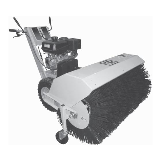
- Page 1 OPERATOR’S and PARTS MANUAL Model MCD-WB Walk-Behind Power Broom M-B Companies, Inc. 1615 Wisconsin Ave. P. O. Box 200 New Holstein, WI 53061-0200 (920) 898-1560 or 800-558-5800 Publication: MCD-WB 031612 FAX: (920) 898-4588 Copyright 2012...
-
Page 3: Table Of Contents
Debris Box Installation ..................15 aDjustMents anD serViCe Speed Selector Adjustment..................17 Broom Drive Tension ....................17 Traction Drive Tension ..................17 Easy Turn Cable Adjustment................18 Shear Pin Replacement ..................18 Belt Replacement....................19 Brush Segment Replacement ................20 Publication: MCD-WB 021512 M-B Companies, Inc. Copyright 2012... - Page 4 Table of conTenTs MaintenanCe Maintenance Schedule ..................23 Lubrication ......................23 Checking Tire Pressure..................24 storage Temporary ......................25 Long Term ......................25 Starting After Long Term Storage .................25 trouBleshooting ....................27 serViCe Parts ......................29 Parts lists .........................30 Warranty DraWings Publication: MCD-WB 021512 M-B Companies, Inc. Copyright 2012...
-
Page 5: Operator's Manual
The broom head serial number plate/decal can be found in the location shown in Figure 1. Record the serial number in the space provided. Broom Serial Number: Figure 1. Publication: MCD-WB 122711 M-B Companies, Inc. Copyright 2011... - Page 6 This Page Intentionally Blank Publication: MCD-WB 122711 M-B Companies, Inc. Copyright 2011...
-
Page 7: Safety Alerts
• Always look down and behind before and while traveling in reverse. • Be aware of discharge direction and do not point discharge at any- one. Do not point the discharge at glass enclosures, automobiles, or windows. Publication: MCD-WB 111511 M-B Companies, Inc. Copyright 2011... -
Page 8: Slope Operation
STOP in an Emer- gency. • Do not shift to neutral and coast down hills. NOTE: All reference to left, right, front, or rear are given from the operator position and facing forward. Publication: MCD-WB 111511 M-B Companies, Inc. Copyright 2011... -
Page 9: Children
• Frequently check components and replace with manufacturer’s 2. Exercise extreme caution when operating on or crossing gravel recommended parts, when necessary. drives, walks, or roads. Stay alert for hidden hazards or traffic. Publication: MCD-WB 111511 M-B Companies, Inc. Copyright 2011... -
Page 10: Maintenance And Storage
16. Never operate the power broom without good visibility or light. Always be sure of your footing, and keep a firm hold on the handles. Walk, never run. Publication: MCD-WB 111511 M-B Companies, Inc. Copyright 2011... -
Page 11: Controls And Features
Publication: MCD-WB 070111 M-B Companies, Inc. Copyright 2011... - Page 12 This Page Intentionally Blank Publication: MCD-WB 070111 M-B Companies, Inc. Copyright 2011...
-
Page 13: Checks Before Each Start-Up
Proper footwear is recommended for gasoline away from open flame or the operator to help prevent slipping. spark. never attempt to operate on exces- sively steep slopes. the maximum slope for any operation is 17.7% (10º). Publication: MCD-WB 122111 M-B Companies, Inc. Copyright 2011... -
Page 14: Ground Speed Selector
There are five forward speeds and two reverse speeds. To change speeds, release both control levers (B, Figure 2), then move the Speed Selector to the desired setting. Fully depress the control levers to resume. Publication: MCD-WB 122111 M-B Companies, Inc. Copyright 2011... -
Page 15: Brush Height Adjustment
Loosen the caster wheel lock lever. (See A, Figure 5) b. Raise or lower the caster wheel as needed. c. Tighten the caster wheel lock lever. NOTE: If using the power broom for turf applications, less ground contact is required. Publication: MCD-WB 122111 M-B Companies, Inc. Copyright 2011... - Page 16 Pin in outer hole (freewheel) NOTE: Be sure both wheels are locked (locking pin in inner hole) when clearing snow. B. Pin in inner hole (Drive) Figure 7. Traction Lock Pin - RH Wheel Publication: MCD-WB 122111 M-B Companies, Inc. Copyright 2011...
-
Page 17: Turf Caster Installation
7. Insert hitch pin (5) to secure the broom assembly to the debris box. Install hairpin cotter pin (4) to secure the hitch pin. Figure 1. Turf Caster Assembly Publication: MCD-WB 070111 M-B Companies, Inc. Copyright 2011... - Page 18 8. The final assembly is shown in Figure 4. 9. Adjust the broom height to according to the Brush Height Adjust- ment procedure within the OPERATION section. Figure 4. Debris Box Installed on Power Broom Figure 3. Debris Box Installation Publication: MCD-WB 070111 M-B Companies, Inc. Copyright 2011...
-
Page 19: Speed Selector Adjustment
6. Release Broom Control. Broom must stop within 5 seconds. to remedy, loosen tension on clutch 7. If broom does not operate properly, stop engine and recheck cable slightly, and recheck. drive linkage adjustments. Publication: MCD-WB 120511 M-B Companies, Inc. Copyright 2011... -
Page 20: Easy Turn Cable Adjustment
(Use of bolts, screws or a harder shear pin will lead to damaged equipment. 2. Install new shear pin(s) and secure with nut. Figure 5. Shear Pin Replacement Publication: MCD-WB 120511 M-B Companies, Inc. Copyright 2011... -
Page 21: Belt Replacement
The arm for the front idler pulley (G, Figure 7) may have to be pivoted to provide clearance for removing the belt from the traction pulley. c. Pull the belt out between the broom pulley (F, Figure 7) and traction pulley. Publication: MCD-WB 120511 M-B Companies, Inc. Copyright 2011... -
Page 22: Brush Segment Replacement
Belt stops C. idler Pulley f. Broom Pulley Belt stops a. end Plate C. engagement fingers Figure 9. Belt Pattern (viewed from front) B. Brush segment Figure 11. Brush Assembly Publication: MCD-WB 120511 M-B Companies, Inc. Copyright 2011... - Page 23 Align segment engagement fingers (C, Figure 11) on alter- nating support shafts. This will evenly spread rotating force through the drive system. 8. Reinstall broom assembly. IMPORTANT! Fully tighten the bearing setscrews before operating the power broom. Publication: MCD-WB 120511 M-B Companies, Inc. Copyright 2011...
- Page 24 This Page Intentionally Blank Publication: MCD-WB 120511 M-B Companies, Inc. Copyright 2011...
-
Page 25: Maintenance Schedule
Disassemble parts to apply grease to moving parts when grease fittings are not installed. Oil locations indicated by oil can symbol. Do not allow oil to drip onto traction drive or friction disc. Figure 2. Drive Lubrication Publication: MCD-WB 070111 M-B Companies, Inc. Copyright 2011... -
Page 26: Checking Tire Pressure
Be sure to keep caps on valves to prevent entry of debris into the valve stem when tires are filled. Figure 3 Figure 4 Publication: MCD-WB 070111 M-B Companies, Inc. Copyright 2011... -
Page 27: Temporary
To avoid this condition, add a gasoline stabilizer to the fuel tank or drain all fuel from the system before plac- ing unit in storage. Publication: MCD-WB 070111 M-B Companies, Inc. Copyright 2011... - Page 28 This Page Intentionally Blank Publication: MCD-WB 070111 M-B Companies, Inc. Copyright 2011...
-
Page 29: Troubleshooting
Speed selector difficult to move or 1. Hex shaft needs lubrication. 1. Lubricate hex shaft with 5W-50 synthetic frozen in place. motor oil (see Maintenance). Publication: MCD-WB 070111 M-B Companies, Inc. Copyright 2011... - Page 30 This Page Intentionally Blank Publication: MCD-WB 070111 M-B Companies, Inc. Copyright 2011...
-
Page 31: Service Parts
Please have your serial number (S/N) ready when contacting M-B Co. or an Authorized Dealer for replacement parts or service information. M-B Co. website: www.m-bco.com 1615 Wisconsin Ave. email: sales@m-bco.com P.O. Box 200 Phone: 800-558-5800 or 920-898-4203 New Holstein, WI 53061-0200 FAX: Main 920-898-4588 Attachments 920-898-1085 Brush Dept. 920-898-1082 Publication: MCD-WB 010912 M-B Companies, Inc. Copyright 2012... -
Page 32: Parts Lists
Broom Final Drive Publication: MCD-WB 031612 M-B Companies, Inc. Copyright 2012... - Page 33 HEX HEAD CAPSCREW, 5/16-18 x 3/4" 341-20000 WASHER, FLAT, 5/16" 505-129571 SHEAVE, BELT, 6" OD, 3/4" ID 410-140536 FRAME, MOUNTING 380-140544 PIN, SWING, TRIGGER RELEASE 387-140764 MOUNT BASE, CABLE 371-160349 CAGE NUT, SQUARE, 5/16"-18 Publication: MCD-WB 031612 M-B Companies, Inc. Copyright 2012...
- Page 34 This Page Intentionally Blank Publication: MCD-WB 031612 M-B Companies, Inc. Copyright 2012...
- Page 35 HHCS, Serrated Flange, 3/8-16 x 1 Plated, 3' or 4' Brush 401-147887 Plate, End Retainer, 3' or 4' Brush 410-132213 Core, W.U., Thru Shaft Tri, 3' Brush 410-140473 Core, W.U., Thru Shaft Tri, 4' Brush Publication: MCD-WB 031612 M-B Companies, Inc. Copyright 2012...
- Page 36 Broom Head Assembly Publication: MCD-WB 031612 M-B Companies, Inc. Copyright 2012...
- Page 37 410-140974 BRUSH FRAME - W.U. 3' BRUSH 410-147146 BRUSH FRAME - W.U. 4' BRUSH 501-140152 GEARBOX, WORM, ALUMINUM, 8.25:1 600-132225 FLANGETTE BEARING 711-132229 PLUG, SQUARE, 1" PLASTIC 711-132230 TUBE PLUG, SQUARE, 2" Publication: MCD-WB 031612 M-B Companies, Inc. Copyright 2012...
- Page 38 To adjust traction and broom control linkage with drive levers engaged, the bottom end of lower rods (Ref. 33 and 44) should be flush with bottom of springs (Ref. 32 and 46). Publication: MCD-WB 031612 M-B Companies, Inc. Copyright 2012...
- Page 39 NUT, Hex Machine Screw 10-24 NC-2B 1707452 SPRING, Extension 3-11/32 Long 1668526 ROD, Clutch, 6-5/16 Long 1722460 PIN, Quick 1666255 ROD, Lower Shift 15-21/64 Long 1931317 CARRIAGE BOLT, 1/4-20 x 3/4 G5 Publication: MCD-WB 031612 M-B Companies, Inc. Copyright 2012...
- Page 40 To adjust traction and broom control linkage with drive levers engaged, the bottom end of lower rods (Ref. 33 and 44) should be flush with bottom of springs (Ref. 32 and 46). Publication: MCD-WB 031612 M-B Companies, Inc. Copyright 2012...
- Page 41 CAPSCREW, Hex Flange Whiz Lock 5/16-18 x 1-1/2 1919326 WASHER, 5/16 1702662 LEVER, Clutch 1702552 SPACER, 21/64 ID x 3/4 OD x 53/64, Powdered Metal 1960685 NUT, Hex KEPS, 1/4-20 Conical Washer Publication: MCD-WB 031612 M-B Companies, Inc. Copyright 2012...
- Page 42 1040 Shift rod assembly (Ref. 310) must pivot 0370 freely on pivot blocks 1810 (Ref. 320). 1030 0980 1030 Mount clutch cable to cable support, see Engine & Frame. 0390 0980 0400 Publication: MCD-WB 031612 M-B Companies, Inc. Copyright 2012...
- Page 43 1931317 BOLT, Round Head, Short Neck 1/4-20 x 3/4 1040 1732470 KNOB 1100 1718791 CABLE & HANDLE ASSEMBLY 1150 1664022 GROMMET, 1/2 1200 1725702 SCREW, PAN HEAD 1400 1668608 GRIP, HANDLE CLUTCH Publication: MCD-WB 031612 M-B Companies, Inc. Copyright 2012...
- Page 44 1040 Shift rod assembly (Ref. 310) must pivot 0370 freely on pivot blocks 1810 (Ref. 320). 1030 0980 1030 Mount clutch cable to cable support, see Engine & Frame. 0390 0980 0400 Publication: MCD-WB 031612 M-B Companies, Inc. Copyright 2012...
- Page 45 REF NO. PART NO. QTY. DESCRIPTION 1430 1724489 PLUG, Button 1730 1960074 CLIP, Hair Pin 1800 1735148 CABLE & SPRING ASSEMBLY, RH 1810 1728115 CABLE & SPRING ASSEMBLY, LH 1830 1677453 ROD, CONTROL Publication: MCD-WB 031612 M-B Companies, Inc. Copyright 2012...
- Page 46 Shift rod assembly (Ref. 0270) must pivot 0310 freely on pivot blocks 0060 (Ref. 0350). 0300 0260 0020 0300 0380 Mount clutch cable to cable support, see Engine & Frame. 0320 0260 0330 Publication: MCD-WB 031612 M-B Companies, Inc. Copyright 2012...
- Page 47 BOLT, CARRIAGE, 1/4-20 x 3/4" 0310 1734388 ROD, SHIFT, UPPER, 11.5" Long 0320 1666255 ROD, SHIFT, LOWER, 15.32" Long 0330 1722460 PIN, QUICK 0340 1924361 WASHER, FLAT, 1/2" 0350 1668524 BLOCK, PIVOT 0360 1668681 WASHER, CURVED Publication: MCD-WB 031612 M-B Companies, Inc. Copyright 2012...
- Page 48 Shift rod assembly (Ref. 0270) must pivot 0310 freely on pivot blocks 0060 (Ref. 0350). 0300 0260 0020 0300 0380 Mount clutch cable to cable support, see Engine & Frame. 0320 0260 0330 Publication: MCD-WB 031612 M-B Companies, Inc. Copyright 2012...
- Page 49 REF NO. PART NO. QTY. DESCRIPTION 0370 1734696 ROD & ARM ASSEMBLY, SHIFT CONTROL 0380 1960729 SCREW, HEX HEAD, 5/16-18 x 1" 0400 1960074 CLIP, HAIR PIN 0410 1668185 BUSHING, 1/2 x 3/4 x 1/4" Publication: MCD-WB 031612 M-B Companies, Inc. Copyright 2012...
- Page 50 Position Belt Stops (Ref. No. 470) 1/16" - 1/8" 0470 0500 from belt when broom drive is engaged. 1240 Torque engine mounting hardware (Ref. No. 0210 and 0220) to 17 - 21 ft. lbs. (23 - 29 Nm). Publication: MCD-WB 031612 M-B Companies, Inc. Copyright 2012...
- Page 51 COVER, BELT 1260 1930540 SCREW, SET, SQUARE HEAD, 5/16-18 x 5/8" 1270 1924940 WASHER, FLAT, 3/8" (S/Ns 2013226186 and up) 1280 1667811 SPACER (S/Ns 2013226186 and up) 1290 504-132341 V-BELT, BROOM DRIVE Publication: MCD-WB 031612 M-B Companies, Inc. Copyright 2012...
-
Page 52: Traction Drive
Ref. No. 0020 & 0120. 0130 Assemble Ref. 0210, 0030 & 0050 with no end play. Parts must 0140 0290 0090 rotate freely. 0100 0120 Grease bearing area of Ref. No. 0120. Publication: MCD-WB 031612 M-B Companies, Inc. Copyright 2012... - Page 53 SPROCKET, 36-TOOTH 0310 1718687 GEAR, DOUBLE D, 10-TOOTH 0320 1921333 CAPSCREW, HEX HEAD, 5/16-18 x 1" G5 0330 1960684 NUT, HEX KEPS, 5/16"-18, CONICAL WASHER 0340 1667341 RETAINER, BEARING 0350 1705897 BEARING, BALL Publication: MCD-WB 031612 M-B Companies, Inc. Copyright 2012...
- Page 54 Ref. No. 0020 & 0120. 0130 Assemble Ref. 0210, 0030 & 0050 with no end play. Parts must 0140 0290 0090 rotate freely. 0100 0120 Grease bearing area of Ref. No. 0120. Publication: MCD-WB 031612 M-B Companies, Inc. Copyright 2012...
- Page 55 CHAIN, ROLLER 0550 1960687 LOCK NUT, HEX FLANGE, 3/8"-16 0580 1736222 RING, RETAINING, EXTERNAL, #87 0590 1919326 WASHER, 11/32 x 3/4 x 1/16" 0600 1666425 BUSHING 0610 1666855 BUSHING 0620 1665521 BEARING, BALL Publication: MCD-WB 031612 M-B Companies, Inc. Copyright 2012...
- Page 56 This Page Intentionally Blank Publication: MCD-WB 031612 M-B Companies, Inc. Copyright 2012...
- Page 57 REF NO. PART NO. QTY. DESCRIPTION 0015 1714235 WHEEL & TIRE ASSEMBLY, RH 0070 1612000 TIRE 0080 1714242 WHEEL 0010 1720306 WHEEL & TIRE ASSEMBLY, LH 0020 1731186 PIN, Klik 0120 1612000 TIRE 0130 1720307 WHEEL Publication: MCD-WB 031612 M-B Companies, Inc. Copyright 2012...
- Page 58 Beginning with drive unit S/N 2014627501, the serial number decal is located on the outside rear of the bottom cover, between the handlebar supports. Publication: MCD-WB 031612 M-B Companies, Inc. Copyright 2012...
- Page 59 1714245 Decal, R1 Ground Speed 390-118356 Decal, Grease Point 390-118348 Decal, DANGER, Falling 390-118349 Decal, DANGER, No Riders 390-118351 Decal, CAUTION, Read Operator’s Manual 390-118355 Decal, M-B Refills 390-118354 Decal, Brush Pattern Publication: MCD-WB 031612 M-B Companies, Inc. Copyright 2012...
- Page 60 Decals Publication: MCD-WB 031612 M-B Companies, Inc. Copyright 2012...
- Page 61 Decals REF NO. PART NO. QTY. DESCRIPTION 390-118352 Decal, WARNING, Moving Parts Hazard 390-118353 Decal, DANGER, Pinch Hazard 390-117897 Decal, M-B Publication: MCD-WB 031612 M-B Companies, Inc. Copyright 2012...
- Page 62 Debris Box Assembly (Option) Publication: MCD-WB 031612 M-B Companies, Inc. Copyright 2012...
- Page 63 ADAPTER, MOUNTING, LEFT 410-147114 ADAPTER, MOUNTING, RIGHT 410-140378 FRAME, 3' 410-147347 FRAME, 4' 410-140414 DEBRIS BOX, 3' 410-147344 DEBRIS BOX, 4' 711-132229 PLUG, SQUARE, 1" 371-92058 LOCK NUT, FLANGE, SERRATED, 1/4"-20 390-117897 M-B DECAL Publication: MCD-WB 031612 M-B Companies, Inc. Copyright 2012...
- Page 64 Sprinkler Kit (Option) Cut 1" wide foam tape (included in Kit) and adhere to bracket (40) surface in contact 24 19 with hood (2 places). Adhere label 390-92009 (included in Kit) to plate (26). Publication: MCD-WB 031612 M-B Companies, Inc. Copyright 2012...
- Page 65 Bar, Spray, 4' 268-00020 Barb Adapter, Male Pipe, 3/8" Hose x 3/8" NPT 370-74138 U-Bolt, 3/4" ID, 1/4"-20 217-97161 Cap, Pipe, 3/4" 311-20750 Capscrew, Hex Head, 5/16-18 x 3/4" 351-20000 Washer, Lock, 5/16" Publication: MCD-WB 031612 M-B Companies, Inc. Copyright 2012...
- Page 66 Sprinkler Kit (Option) Cut 1" wide foam tape (included in Kit) and adhere to bracket (40) surface in contact 24 19 with hood (2 places). Adhere label 390-92009 (included in Kit) to plate (26). Publication: MCD-WB 031612 M-B Companies, Inc. Copyright 2012...
- Page 67 Sprinkler Kit (Option) REF NO. PART NO. QTY. DESCRIPTION 341-20000 Washer, Flat, 5/16" 371-81417 Nut, Lock, 1/2"-13 341-50000 Washer, Flat, 1/2" 311-53000 Capscrew, Hex Head, 1/2-13 x 3" 401-140744 Bracket, Tank Support Publication: MCD-WB 031612 M-B Companies, Inc. Copyright 2012...
- Page 68 ± 0.06 inches 3.19 1.57 1.66 2.25 3.19 1.57 1.66 2.25 (81) (40) (42) (27) (81) (40) (42) (27) Consult factory if precise details are required. 3.94 6.37 3.94 6.80 (100) (162) (100) (173) Publication: MCD-WB 031612 M-B Companies, Inc. Copyright 2012...
-
Page 69: Troubleshooting
Tel: +49-40-53 53 73-0 Fax: (949) 859-1153 Fax: +44 (0) 1992 467132 Fax: (519) 821-2569 Fax: 045-475-8908 Fax: +49-40-53 53 73-11 © Copyright 2001, ITT Industries Printed in U.S.A. All Rights Reserved Form: 81000-312 11/01 Publication: MCD-WB 031612 M-B Companies, Inc. Copyright 2012... - Page 70 100-92156 FORK ASSEMBLY, CASTER (Includes wheel sleeve bearing, attachment bolt and nut.) 370-92047 CARRIAGE BOLT, 3/8-16 x 1" (Fork to Mount) 341-30000 WASHER, FLAT, 3/8" 361-30000 HEX NUT, 3/8-16 410-132595 MOUNT, CASTER Publication: MCD-WB 031612 M-B Companies, Inc. Copyright 2012...
- Page 71 LIMITED WARRANTY Limited Warranty: Subject to the limitations set forth herein, M-B Companies, Inc. (“M-B”) warrants its products to be free from defects in material and workmanship for a period of twelve (12) months from the date of delivery of the product to its original owner, except that the warranty is twelve (12) months solely for the following products: Truck Mounted Pavement Marking Equipment, Airport Snow Removal Products, Attachment Products, Brushes, MSV Multi-Service Vehicles.
- Page 72 M-B Companies, Inc. 1615 Wisconsin Ave. P. O. Box 200 New Holstein, WI 53061-0200 (920) 898-1560 or 800-558-5800 FAX: (920) 898-4588...
Need help?
Do you have a question about the MCD-WB and is the answer not in the manual?
Questions and answers