Table of Contents
Advertisement
MTH
ELECTRIC TRAINS, INC.
7020 Columbia Gateway Drive
Columbia, MD 21046-1532
O-31
S
®
MTH RealTrax switches add flexibility
and reliability to your O Gauge RealTrax
layout. Designed to provide years of
trouble free, smooth operation, RealTrax
W
®
I
T
switches are the
perfect additions
to expand your
®
RailKing empire.
C
H
Advertisement
Table of Contents

Subscribe to Our Youtube Channel
Summary of Contents for MTHTrains RealTrax O-3
- Page 1 ® ELECTRIC TRAINS, INC. 7020 Columbia Gateway Drive ® MTH RealTrax switches add flexibility Columbia, MD 21046-1532 and reliability to your O Gauge RealTrax layout. Designed to provide years of trouble free, smooth operation, RealTrax switches are the perfect additions to expand your ®...
-
Page 2: Table Of Contents
Table of Contents Introduction: Switch Operating Instructions: ® RealTrax O-31 Switch Components: Screw Terminal Definition: Remote Switch Wiring Instructions: Basic Switch Operation: Changing Switch Block Positions: Accessory Operation From Switch Power Out: Multiple Connections Under Screw Terminal Multiple Switch Operating Instructions (Track Power): Multiple Switch Operation Through One Remote Switch, Track Power, Identical Throws: Multiple Switch Operation Through One Remote Switch,... -
Page 3: Introduction
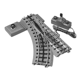
Introduction Thank you for purchasing the MTH Electric Trains RealTrax O-31 Switch. As with all RealTrax products, you will find the O-31 Switch easy to install into your layout whether it be a permanent or temporary one. There are no plastic and/or metal pins to lose or confuse. -
Page 4: Switch Operating Instructions
® RealTrax O-31 Switch Operating Instructions: RealTrax O-31 Switch Components: 1) Switch: Consists of the roadbed, rails, points, frog, screw terminals, operating circuitry and mechanisms. 2) Screw Terminal Cover: Plastic cover that attaches to the roadbed and conceals the screw terminals. 3) Jumper: Removable metal connector between 4th and 5th screw terminals. - Page 5 Figure 1a:...
-
Page 6: Screw Terminal Definition
Screw Terminal Definition There are five Screw Terminals located under the Screw Terminal Cover on the straight edge of every RealTrax Switch. The positions of the Screw Terminals on a Right-Hand Switch mirror those on the Left-Hand Switch (see figure 1b, below). Figure 1b: Straight AC Screw Terminal Curved AC Screw Termial... -
Page 7: Remote Switch Wiring Instructions
Remote Switch Wiring Instruction You will have to wire the RealTrax O-31 Remote Control Switch to the proper Screw Terminals. To do this, follow Illustration 2: Figure 2: (REMOTE SWITCH) (SCREW TERMINAL COVER) Connect the GREEN wire of the REMOTE SWITCH to the Straight AC SCREW TERMINAL (found under the removable SCREW TERMINAL COVER). -
Page 8: Changing Switch Block Positions
Changing Switch Block Position: Figure 4: To change the position of the Switch Block, follow the steps below: 1) Remove the Switch Block by pulling it firmly out of the roadbed. Remove the Switch Block Cover by sliding it down out of the roadbed. 2) Install the Switch Block into the other side by pushing it firmly into the roadbed. -
Page 9: Accessory Operation From Switch Power Out
Accessory Operation from Switch Track AC Out Screw Terminal: Figure 5: Track AC out Connect the ACG (Common) terminal of the accessory to the ACG (Common) screw terminal of the Switch. Connect the AC (Powered) terminal of the accessory to the Track AC Out screw terminal of the Switch. -
Page 10: Multiple Switch Operation Through One Remote Switch
Multiple switch operation through one Remote Switch (track power, simultaneous opposite throws): Figure 8: Primary Switch To Remote Switch Secondary Switch Connect Remote Switch as shown in Figure 2. Connect the STRAIGHT AC screw terminal of the Primary Switch to the CURVED AC screw terminal of the Secondary Switch. -
Page 11: Multiple Switch Operation Through Separate Remote Switches
Auxiliary power operation of multiple switches through separate Remote Switches (separate throws): Figure 10: Primary Switch To Remote Aux. AC Power In (Red) Switch To Remote Aux. ACG (Common)(Black) Switch Secondary Switch Remove Jumpers from all auxiliary powered switches. Connect Remote Switches as shown in Figure 2. Connect Auxiliary Power ACG (Common) to all auxiliary powered switch ACG screw terminals, either in series (from one Switch ACG terminal to the next, as shown) or in parallel (each Switch ACG terminal... - Page 12 Auxiliary power operation of multiple switches through single Remote Switch (simultaneous opposite throws): To Remote Switch Figure 12: Primary Switch Aux. AC Power In (Red) Aux. ACG (Common)(Black) Secondary Switch Remove Jumpers from all auxiliary powered switches. Connect Remote Switch to primary switch as shown in Figure 2. Connect Auxiliary Power AC to Auxiliary Power AC In screw terminal of primary switch.
-
Page 13: Realtrax O-31 Switches In Tubular Rail Layouts
® RealTrax O-31 Switches In Tubular Rail Layouts: The RealTrax O-31 Switch can be installed into O-Gauge tubular rail layouts with the use of three RealTrax Adapter Track sections. Simply attach one Adapter Track section (5" long) to each arm of the RealTrax O-31 Switch. The steel pins of your tubular track will insert into the tubular rail portion of the RealTrax Adapter Track. -
Page 14: Multiple Train Operation Using Powered/Unpowered Sidings
Multiple Train Operation (Powered/Unpowered Siding) The following layout wiring diagram illustrates the use of two switches wired for simultaneous operation, identical throw. With this wiring arrangement, you will be able to operate two trains on your layout without collision (provided that no part of either consist obstructs the “Main Line” portion of the layout). -
Page 15: Troubleshooting
Wiring Instructions: 1) Connect the Powered (Red) transformer output to the Powered (Red, center rail) terminals of the Main Line, “A” Line and “B” Line lock-ons. 2) Connect the Common (Black) transformer output to the Common (Black, outside rail) terminal of the Main Line lock-on. 3) Connect the Common (Black) transformer output to the input side of a Single-Pole, Double Throw (SPDT) switch (purchased separately). -
Page 16: Service And Warranty Information
CAUTION - ELECTRICALLY OPERATED PRODUCT: Not recommended for children under eight years of age without adult supervision. As with all electric products, precautions should be observed during handling and use to reduce the risk of electric shock. WARNING: When using electrical products, basic safety precautions should be followed including the following: Read this manual thoroughly before using this device.
Need help?
Do you have a question about the RealTrax O-3 and is the answer not in the manual?
Questions and answers