Table of Contents
Advertisement
Quick Links
HOME-PRO 3000
Assembly and Mounting Instructions - May 2010
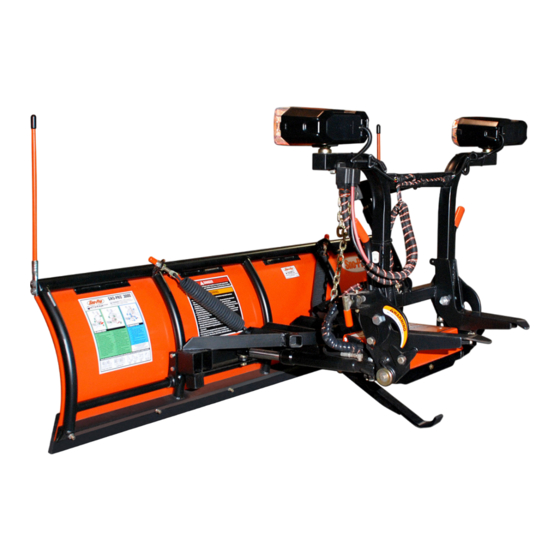
Home-Pro 3000 Series Polymer Moldboard Plow
7' Moldboard PN: 1SP7 ● 7-1/2' Moldboard PN: 1SP75HP
Curtis Industries Inc. LLC, 111 Higgins St., Worcester, MA 01606 TEL: (800) 343-7676 FAX: (508) 854-3377 For Parts and information visit us at www.Curtisindustries.net
Curtis Industries Inc. LLC, reserves the right to change product design or specifications without notice or liability.
Curtis Snow Plows are protected by the following U.S. Patent Numbers: 6,145,222 and 6,209,231 Licensed under U.S. Patent Number 5,568,694 & Canadian Patent Number 2,137,853.
Other patents pending.
1 of 25
Advertisement
Table of Contents

Summary of Contents for Sno-Pro 1SP7
- Page 1 Assembly and Mounting Instructions - May 2010 Home-Pro 3000 Series Polymer Moldboard Plow 7' Moldboard PN: 1SP7 ● 7-1/2' Moldboard PN: 1SP75HP Curtis Industries Inc. LLC, 111 Higgins St., Worcester, MA 01606 TEL: (800) 343-7676 FAX: (508) 854-3377 For Parts and information visit us at www.Curtisindustries.net Curtis Industries Inc.
-
Page 2: Required Tools
Curtis Plows are simple by design. Our unit utilizes an A-Frame assembly for mounting the Electric/Hydraulic unit. This exclusive Curtis feature eliminates the need for Hydraulic Quick-disconnects and also "Hides-Away" our Power unit. Our A-Frame assembly takes the weight of the Power unit off the Lift Frame assembly and allows for increased airflow to the Radiator. - Page 3 Home-Pro 3000 Illustrated Parts List - Moldboard & Trip Frame Moldboard/Trip Frame Parts List Ref # Item # Item Description Qty. 1TBP21I 7' HOME-PRO MOLDBOARD 1TBP21K 7.5' HOME-PRO MOLDBOARD 1TBP124 HOME-PRO MOLDBOARD SKIN HMW PLASTIC - 7' 1TBP124-90HP HOME-PRO MOLDBOARD SKIN HMW PLASTIC - 7.5' 1TBP37 BLADE MARKER 1TBP34...
- Page 4 Home-Pro 3000 Illustrated Parts List - A-Frame & Harness PLOW SIDE TRUCK SIDE Apply Grease Apply Grease Inside A-Frame 4 of 25...
- Page 5 Home-Pro 3000 Illustrated Parts List - A-Frame & Harness A-Frame/Harness Parts List Ref # Item # Item Description Qty. 1TBP29C A-FRAME ASSEMBLY COMPLETE 8SV-NAFW-B5 A-FRAME ASSEMBLY - FRAME ONLY 1TBP58A A-FRAME COVER, SnoPro 3000 1TBP30 5/16" x 24" CHAIN 1TBP31 5/16"...
- Page 6 Home-Pro 3000 Illustrated Parts List - Lift Frame 6 of 25...
- Page 7 SNAP LOCK SPRING (INCLUDED IN 9SV-SLH KIT) 1TBP103 PLASTIC HANDLE FOR SNAP LOCK SP3000 (INCLUDED IN 9SV-SLH KIT) 1TBP112A LIFT FRAME SIDE PLATE, LH SNO-PRO 3000 (INCLUDED IN 8SV-TBP112-B5 KIT) 1TBP112B LIFT FRAME SIDE PLATE, RH SNO-PRO 3000 (INCLUDED IN 8SV-TBP112-B5 KIT) 1TBP39H...
- Page 8 Home-Pro 3000 Illustrated Parts List - Hydraulics KTI Hydraulics - Aluminum End Head 10 11 SPX Hydraulics STYLE STYLE OLDER MODELS ONLY 8 of 25...
-
Page 9: Hydraulics Parts List
COLLECTOR MAGNET (INCLUDED IN 9SV-FLT FILTER KIT) 1TBM29 SUCTION COVER (INCLUDED IN 9SV-FLT FILTER KIT) 1TBM23A RESERVOIR - SNO-PRO 3000 W/ MTNG SCREWS (INCLUDED IN 9SV-RES KIT) 1TBM11 SPX RESERVOIR O-RING (INCLUDED IN 9SV-RES KIT) 1TBP63B RESERVOIR CAP - INTERNAL (3/8" BRONZE) (INCLUDED IN 9SV-RES KIT) -
Page 10: Section 1. Moldboard Assembly
Home-Pro 3000 Assembly Instructions Section 1. Moldboard Assembly A.) Lay Moldboard on its face. Place cardboard under the Top Tube to prevent paint damage. B.) Bolt the Trip Frame to the Moldboard at the (6) Pivot Brackets. Figure 1. Figure 1. Bolt Trip Frame to Moldboard Section 2. -
Page 11: Section 3. Mount A-Frame To Trip Frame
Home-Pro 3000 Assembly Instructions Section 3. Mount A-Frame to Trip Frame A.) With Moldboard remaining face down, lift A-Frame assembly over the Trip Frame (with assistance, A-Frame is very heavy) and lower it into the center hole of Trip Frame. Apply grease and install (1) 1"... -
Page 12: Section 4. Lift Frame Side Plate Install
Home-Pro 3000 Assembly Instructions Figure 4. Connect Angle Ram Cylinders to Trip Frame 1" x 4" Clevis Pin 1" x 4" Clevis Pin 3/16" x 2" Cotter Pin Section 4. Lift Frame Side Plate Install A.) Locate both L&R Lift Frame Side Plates (1TBP112A&B) and slide (1) onto each side of the A-Frame Hinge Pin. - Page 13 Home-Pro 3000 Assembly Instructions Figure 5. Lift Frame Side Plate Installation Torsion Spring and Bushing Right Lift Frame Side Plate Left Lift Frame Side Plate Torsion Spring and Bushing Figure 6. Attach Lift Chain and Mount Blade Markers Mount Blade Markers Chain Shackle Cotter Pin 13 of 25...
-
Page 14: Section 5. Mount Lift Frame To A-Frame Side Plates
Home-Pro 3000 Assembly Instructions Section 5. Mount Lift Frame to A-Frame Side Plates A.) With assistance, position Lift Frame to Side Plates and mount with (4) 5/8"-18 x 1-3/4" Bolts and 5/8"-18 Lock Nuts. To provide proper clearance, 5/8" Bolts must be installed from the inside of Lift Frame with Lock Nuts located on the outside of Lift Frame. -
Page 15: Section 6. Lift Frame Setup
Home-Pro 3000 Assembly Instructions Figure 8. Lift Frame Mounting Reference View Left Side Shown 5/8" Locknuts installed on Outside of Lift Frame Spring Keeper on Side Plate Torsion Spring Lift Frame Side Plate Torsion Spring Bushing A-Frame Spring Stop 1/2" Patch Bolt Section 6. - Page 16 Home-Pro 3000 Assembly Instructions Figure 9. Lift Arm Mounting 3/4" x 4-1/2" Clevis Pin 1" x 4-1/2" Secure Clevis Pin with Cotter Pin 3/4" x 2-3/4" Clevis Pin Insert Clevis Pin Cotter Pin through 1" Piston Spacers when mounting Lift Cylinder Insert Cylinder End through Lift Frame Tabs Point Hose Port toward A-Frame...
-
Page 17: Section 7. Harness Steps
Home-Pro 3000 Assembly Instructions Section 7. Harness Steps A.) If Harness and Lift Cylinder Hose are not pre-wrapped together with Hose Wrapping, tie together using (3) Wire Ties 4" apart starting at the A-Frame exit. B.) Secure the Harness to the Lift Frame using supplied Harness Clips, Bolts, Nuts and Wire Ties. C.) Attach Plow Harness to Lift Frame at Tab 'A' using supplied P-Clamp. - Page 18 Home-Pro 3000 Assembly Instructions Figure 12. Secure Harness to Lift Frame Front Left (Driver's Side) of Lift Frame Harness Clip on Tab 'B' Harness Routes behind 1/4" Bolt & Lock Nut To Lift Cylinder 1/4" Bolt & Lock Nut Harness Clip on Tab 'A' Up to Lights Harness Clips...
-
Page 19: Section 8. X Height Procedure
Home-Pro 3000 Assembly Instructions Figure 13. Determine X Height for Correct Side Plate Mounting Holes Section 8. X Height Procedure A.) Install Mount Kit on vehicle referring to Mount Kit installation procedure. Wire vehicle referring to Page 22 for detailed Harness & Control System installation information. B.) With vehicle parked on level ground and properly ballasted for snow plow use, measure the distance from the ground up to the centerline of the Latch Bar on the Receiver as shown. - Page 20 Home-Pro 3000 Assembly Instructions Vehicle to Plow Initial Setup Once Vehicle Mount Kit and Harness installations are complete, raise the Plow to the same level as the Mount Kit Receiver. To accomplish this, drive truck close to Plow and attach the Harness Plug. Put 'In- Cab' Control System into the 'float' position and raise the Plow using the A-Frame Jack Switch to align the rear of the Lift Frame with the Mount Kit Receiver.
-
Page 21: Section 9. Plow Light Beam Aiming Procedure
Home-Pro 3000 Assembly Instructions Section 9. Plow Light Beam Aiming Procedure A.) Vehicle must be on level surface 25 feet in front of matte-white screen, such as a garage door. The screen should be perpendicular to both the ground and vehicle centerline. B.) Vehicle should be ballasted for snow plowing with a driver. - Page 22 Home-Pro 3000 Assembly Instructions Figure 17. Home Pro 3000 Harness Layout Ref.: this is for old style harness p/n 1TBP134 (pre-2009 version) Relay for 2009- NOTE: all valve coils have one orange (ground) wire. 22 of 25...
- Page 23 Home-Pro 3000 Assembly Instructions Figure 18. Home Pro 3000 Control Detail 23 of 25...
- Page 24 Home-Pro 3000 Assembly Instructions Figure 19. Vehicle Side Harness Relay Connector Connections 24 of 25...
-
Page 25: Section 10. Snow Plow Storage
Home-Pro 3000 Assembly Instructions Section 10. Snow Plow Storage A.) When Plow is disconnected, coat all exposed chrome rods on both Angle Ram Cylinders and Lift Cylinder with Light Grease. The Grease will keep exterior surfaces free from rust and corrosion. B.) Whenever Moldboard is disconnected, coat the exposed chrome rods of both Angle Ram Cylinders with Light Grease to protect them from rust and corrosion.
Need help?
Do you have a question about the 1SP7 and is the answer not in the manual?
Questions and answers