
Summary of Contents for Trek 50
- Page 1 OPERATOR’S MANUAL MODEL 50/750 HIGH-VOLTAGE AMPLIFIER TREK INCORPORATED 1 800 367-8735 11601 MAPLE RIDGE ROAD TEL: (585) 798-3140 MEDINA, NY 14103-9710 FAX: (585) 798-3106 www.trekinc.com 50/750 9203...
- Page 2 Thank-you for buying Trek’s Model 50/750 High-Voltage Amplifier. This product has been designed and built to very high standards to give you years of trouble-free service. If you have any questions, please feel free to contact your Trek Representative at: WRITE: TREK, INC.
-
Page 3: Table Of Contents
TABLE OF CONTENTS GENERAL INFORMATION Introduction................1 Specifications ...............2 Incoming Confidence Test ..........3 INSTALLATION Mounting ................4 AC Line Cord Connection..........4 How to Assemble the High Voltage Connector ....4 Load Connections ...............5 Digital Enable Connection..........5 Changing the Output Voltage Range .......6 OPERATION Front Panel Controls and Indicators.........7 Rear Panel Connector ............8 Operating Procedure ............8... -
Page 4: General Information
The Model 50/750 is a high-voltage amplifier The four-quadrant output stage sources or with a 1500-volt output range at 50 mA sinks current into capacitive or resistive loads continuous, 100 mA peak (for 10 µs into anywhere within the output voltage range. - Page 5 0 to +1500 V range or AMPLIFIER INPUT 0 to -1500 V range Less than 50 mV rms to 20 kHz for a 1 nF load (measured with the true rms feature of Input Voltage Range the Hewlett Packard Model 34401A digital 0 to ±10 V DC or peak AC.
-
Page 6: Specifications
BNC coaxial connector. CERTIFICATION Power Requirements Line Supply Trek, Inc. certifies that each Model 50/750 Factory set for one of two ranges: is tested and calibrated to specifications 90 to 127 V AC or 180 to 250 V AC, using measurement equipment traceable at 48 to 63 Hz. -
Page 7: Incoming Confidence Test
Test. Turn off the POWER switch. Discon- or as a -750 V to +750 V amplifier. To test nect the reference power supply and the a 50/750 unit configured as a 0 to -1500 V digital voltmeter. amplifier, substitute the value indicated in parenthesis. -
Page 8: Installation
2. Plug the AC line cord into the AC line cable jacket. cord receptacle on the rear panel. 3. Plug the 50/750 into a 115 V power source. WARNING: Make no attempt to bypass the ground prong in the AC line cord. -
Page 9: Load Connections
DIGITAL ENABLE BNC connector on the contact. the front panel of the POWER SUPPLY module. To control the 50/750 from a CAUTION: Avoid applying excess heat remote device, connect this input to ground to the contact. This will cause the... -
Page 10: Changing The Output Voltage Range
Locating the Programming Plug RANGE Remove the power supply module. The 50/750 output voltage can be pro- programming connector is a white Molex grammed for any of the three output voltage connector that i s located at the rear of the... -
Page 11: Operation
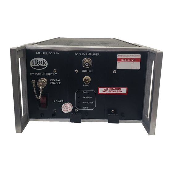
The gain is factory set at 150 V/V 1. POWER Switch: This switch turns the unless otherwise specified when ordered. 50/750 on and off. A red lamp in this switch 6. DAMPING Control: Use this control in assembly glows when the 50/750 is on. -
Page 12: Rear Panel Connector
2. Connect the output of a DC reference supply to the INPUT of the 50/750. OPERATING PROCEDURE 3. Connect the output signal to a digital The 50/750 may be used as either a high- volt-meter. Ensure that the digital voltage amplifier or as a high voltage refer- voltmeter has an input voltage rating ence supply. -
Page 13: Protective Circuitry
Thermal Limiting 2. Monitor the output of the 50/750 with an oscilloscope. Use a compensated high- voltage probe with the oscilloscope if The Model 50/750 is forced-air cooled to necessary to limit the oscilloscope input remove any internal accumulation of heat. -
Page 14: Maintenance
2. Remove and replace the fuses with new other undesirable conditions such as heat- ones of the same style and value. damaged parts. If the 50/750 continually blows fuses, a more CLEANING: Clean the 50/750 as operating serious problem may exist within the conditions require. -
Page 15: Customer Assistance
Trek, Inc. displayed on the shipping container and the packing list, to Trek, Inc. for repair. Telephone assistance is usually effective for obtaining additional maintenance information If we determine that the malfunction is not that is beyond the scope of this manual. -
Page 16: Active Load Limitations
A limitation for the amount of energy that the The amount of energy that can be generated 50/750 can absorb is based on the maximum by the piezoelectric transducer or any active energy that certain components in the load is determined by the formula: 50/750 can dissipate. - Page 17 ZD1 and ZD2 can dissipate, use the active load can be compared to the formula: maximum energy dissipation of the 50/750 for a certain output voltage range. Maximum energy in joules = (V If the energy that can be supplied by the...
Need help?
Do you have a question about the 50 and is the answer not in the manual?
Questions and answers