Table of Contents
Advertisement
Advertisement
Table of Contents
Troubleshooting

Related Manuals for MSV MSAT G2

Summary of Contents for MSV MSAT G2
-
Page 2: Table Of Contents
Introduction ..............Transceiver Unit (TU) . -
Page 3: Introduction
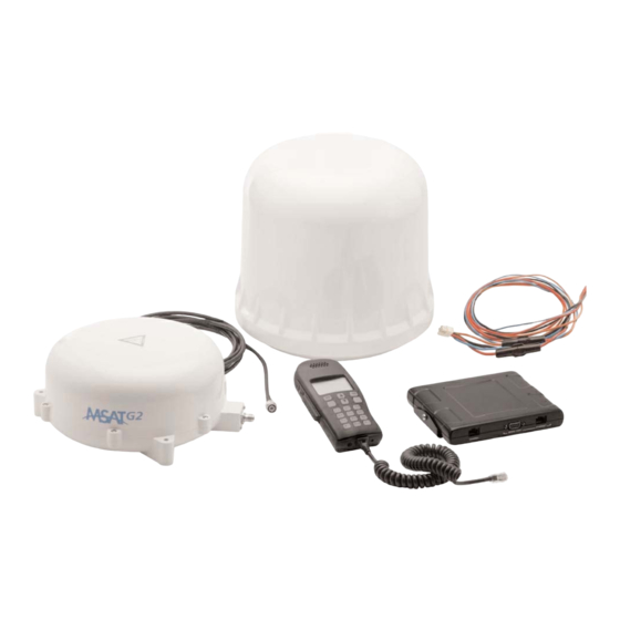
Introduction The purpose of this guide is to provide assistance to personnel installing the new MSAT-G2 mobile satellite radio equipment. The guide starts off by providing installation-specific information on each component of the radio. Installation tips are then offered for fixed-site and vehicular scenarios. - Page 4 An optional external speaker may be connected to the TU for remote monitoring. Serial and ethernet ports are provided for external interfacing, debugging, software upgrading, and future expansion capabilities. Antenna Unit External Speaker External Speaker Antenna Cable Transceiver Unit External Interface Handset Serial Handset Cable...
-
Page 5: Transceiver Unit (Tu)
Transceiver Unit (TU) The TU provides the interface for the handset and antenna unit (AU) and manages the communications over the MSV network. It also distributes power to the handset and Antenna Unit (AU). FRONT BACK Figure 3 - Transceiver Unit w/o Mounting Bracket... -
Page 6: Power Port
The TU is equipped with the following ports: Power Port The power port is the connection from the power supply (vehicle battery or some other 12 VDC power source) to the TU. The power cable has a +12V power line, a +12V ignition sense line, a horn alert line, and a ground line. -
Page 7: Serial Port
Serial Port The serial port is a female DB-9F RS 232 and can be used for NMEA output (GPS) and crossbanding. Pin Data Crossband (currently not supported) CD (Carrier Detect) COR (Carrier Operated Relay) RD (Receive Data) RD (Receive Data) TD (Transmit Data) DTR (Data Terminal Ready) GND (Signal Ground) -
Page 8: Handset Port
Handset Port The RJ45 handset port is used to connect the handset to the TU. The connector type is a modular 8 position and 8 conductor RJ45. The pinout is as follows: Pin Number Signal Name Audio TX + Microphone Audio TX –... -
Page 9: System Power Requirements
Figure 9 – Transceiver Unit Front & Back System Power Requirements There is only one power connection for the entire radio. This must be connected to a 12 VDC power supply. Power requirements and consumption are as follows: Voltage Input Minimum 11.5 V DC Voltage Input Maximum 15.6 V DC... -
Page 10: Power Cable
Power Cable 10 + / - 0 . 5 INCHES VIEW A 6 + / - 0 . 5 INCHES 20 FEET + / - 4 INCHES HORN ALERT AWG 20, STRANDED, BLUE 0.25 A, 1-1/4 BY 1/4 FUSE AWG 16, STRANDED, BLACK 5 A, 1 1/4 BY 1/4 FUSE 12 V IGNITION SENSE... -
Page 11: Standard Cable Connections
Standard Cable Connections In addition to the DC power connection, optional horn alert and ignition sense connections may be made. These are all done using the four wire power cable. In the case of a vehicle installation, the power source is typically the vehicle battery. Cables should be routed appropriately and cable ties and clamps should be used as required to ensure that vibration and/or rubbing of the cables does not occur. -
Page 12: Basic Installation Procedure
Basic Installation Procedure While the installation of the MSAT-G2 mobile satellite radio is straightforward, it is essential that the installation be done correctly. The basic installation procedure is as follows: 1. Decide where you are going to install the antenna, TU and handset. 2. -
Page 13: Lightning Arrestors
Lightning Arrestors The applicable electrical code(s) may require that lightning arrestors capable of supporting L- band transmissions be installed on all cabling between the fixed-site antenna and the structure which the equipment is housed in. It is also suggested that any structure containing the radio be equipped with a lightning rod connected to the ground. - Page 14 TU to the mounting bracket. Not using the supplied bracket screws could result in damage to the TU (especially if screws are too long). MOUNTING HOLE DIMENSIONS BOUNTING BRACKET, MSV Dimensions are in mm Figure 13 - Transceiver Unit Mounting Bracket Dimensions MSAT-G2 Installation Guide...
- Page 15 DIMENSIONS WITH MOUNTING BRACKET MSV TRANSCEIVER UNIT 176.83 33.6 HANDSET SERIAL PORT ETHERNET Dimensions are in mm Figure 14 - Transceiver Unit w/ Mounting Bracket MSAT-G2 Installation Guide...
-
Page 16: The Antenna Unit (Au)
The Antenna Unit (AU) The antenna unit is composed of the antenna element array, necessary high power and low noise amplifier systems, and a tracking system. Two AU versions exist: a 2-axis unit intended for land-mobile and fixed-site installations and a 3-axis unit for the maritime environment. -
Page 17: Spacecom Spac-As-Msv220 Land-Mobile / Fixed-Site Antenna
Do not locate the antenna close to interfering signal sources or receivers. It is recommended that no other antennas be located within three (3) meters of the MSAT-G2 antenna. If there is other equipment installed near the MSAT-G2 satellite radio it is recommended to operate all equipment simultaneously and verify there is no co-interference. - Page 18 Magnetic Mount Installation The Magnet Mount consists of three (3) individual high intensity magnets with rubber coating. Each magnet has a stainless steel M5 center bolt. First attach the magnets to the antenna. There are three (3) “legs” on the antenna where the magnets are placed.
-
Page 19: Permanent (Mast) Mounting
Permanent (Mast) Mounting For permanent mounting of the SPAC-AS-MSV220, a special Pole Mount Installation Kit is available. SpaceCom part no.: SPAC-AC-1017. Designed for easy installation, it ensures proper drainage of the antenna, galvanic insulation and is able to withstand the rigid mechanical stress. Figure 18 –... -
Page 20: Vehicle Mounting
M6X50 screw M6 washer Rubber washer Rubber washer M6 self-locking nut ø U-clamp 44 mm Clamp bracket M8 washer ø U-clamp 50mm M8 self-locking nut Figure 19 – SPAC-AS-MSV220 2-axis Antenna W/ Optional Pole Mount Vehicle Mounting When permanently installing the MSV220 antenna on vehicles, some important guidelines must be followed in order to ensure long and trouble free operation. -
Page 21: Draining The Antenna
Draining the Antenna The antenna is designed with 8 drainage holes in the centre of the bottom portion of the radome. This allows condensation water, if present, to exit the interior of the antenna. To prevent rainwater from entering, the radome is completely sealed except around the drainage holes. -
Page 22: Cleaning
Cleaning The antenna can be cleaned together with the vehicle (hosing down or driving through a washing tunnel). When using a pressure washer, do not direct at the antenna from a short distance. Avoid pressure washing at maximum pressure. This could force water around the sealing gaskets. NEVER direct water, pressurized or not, towards the underside of the radome. -
Page 23: Pole Mount Kit Component Description
Figure 20 – SPAC-AS-MSV320 Maritime Antenna W/ Optional Pole Mount Pole Mount Kit Component Description Mounting Pole Part No. SPAC-M00424 is a piece of standard tubing with a mounting flange welded onto it. The component is made from a stainless steel alloy that is easy to cut, machine and weld. -
Page 24: Spac-As-Msv320 Antenna Installation
Nuts, Part No. SPAC-M90-10105 are M8 nuts used for the clamps, refer to FIG.24 Nuts are to be tightened to 5Nm. Flange, Part No. SPAC-M00430 are used for linking the clamp holding forces. Plug, Part No. SPAC-M00233 is used for partly closing the bottom of the Mounting Pole so that no surge of water will fill the tube or damage any part of the antenna. - Page 25 Vibration levels in a typical installation are usually much less than the above mentioned values. It is, however, the responsibility of the installer to verify that the cited levels are not exceeded in any mode of operation of the vehicle/vessel. In case of abnormal vibration, typically at a resonance frequency, measures must be taken in order to displace the resonance frequency or to dampen the vibration amplitude.
-
Page 26: Installing The Handset
Installing the Handset The handset can be mounted using a standard-sized microphone clip mount (included). Select a mounting position for the handset. The handset should be placed in a location which is easy for the user to see and reach (arm’s length) and which does not impede the user’s movements or vehicle operation. - Page 27 COM: FAILURE - The commissioning process failed. Select YES to re-initiate the commissioning procedure. Contact RETRY? MSV Customer Support if the radio fails to commission after several attempts. Signifies the user has entered an invalid Check that you correctly entered INVALID SASK the SASK.
- Page 28 Signifies the user has entered the Enter the correct password. If the INVALID wrong Dealer or SYSTEM Menu password is unknown, contact MSV PASSWORD password. Customer Support with the radio's ESN. Customer Support can provide a new SYSTEM password.
-
Page 29: Troubleshooting The Installation
Troubleshooting the Installation Steps to Basic Troubleshooting When troubleshooting, always record as much information as possible at all times. Start by asking the person who encountered the problem to describe the problem, the events leading up to the problem and any troubleshooting work that may have been done already. This information will be valuable when discussing the problem with others and will help to debug similar problems in the future. -
Page 30: Troubleshooting Some Typically Encountered Problems
5. Troubleshoot by component Does the problem sound TU-related, antenna-related, handset-related or external equipment-related? Swap out a suspect component into a known working system (i.e. if the TU is suspect, try it out with a known working antenna and handset). It is highly recommended that a complete working satellite radio (TU, Handset, and AU) be part of any troubleshooting kit. -
Page 31: Msat-G2 Technical Specifications
MSAT -G2 Technical Specifications Weight HUGHES 2100 TU = 0.8 lbs DT-200 Handset = 0.6 lbs SPAC-AS-MSV220 Antenna = 4.6 lbs SPAC-AS-MSV320 Antenna = 10.3 lbs Dimensions HUGHES 2100 TU = (W) 6.5” x (H) 1.1” x (D) 5.6” DT-200 Handset = (W) 2.9” x (H) 1.4” x (D) 6.8” SPAC-AS-MSV220 Antenna = (Diameter) 9.8”... - Page 32 All trademarks, marks, names, or product names referenced in this publication are the property of their respective owners, and Mobile Satellite Ventures, LP, neither endorses nor otherwise sponsors any such products or services referred to herein. MSV is a trademark of Mobile Satellite Ventures, LP. MSAT-G2 Installation Guide...
Need help?
Do you have a question about the MSAT G2 and is the answer not in the manual?
Questions and answers