
Related Manuals for Jet Hangar A-7D/E Corsair II

Summary of Contents for Jet Hangar A-7D/E Corsair II
-
Page 1: Assembly Instructions
ASSEMBLY INSTRUCTIONS JET HANGAR INTERNATIONAL, INC. Post Office Box 1607 Hawaiian Gardens, CA 90716 phone: 562-467-0260 fax: 562-467-0261 email: larrywjhi@jethangar.com www.jethangar.com... -
Page 2: Table Of Contents
JHI-A7-06-0001 TABLE OF CONTENTS TO OUR VALUED CUSTOMERS.................4 INTRODUCTION..................5 Operation of R/C Jet Aircraft..............5 The Academy of Model Aeronautics (AMA)..........5 ABOUT THE A-7 CORSAIR II..............5 GENERAL BUILDING TIPS ...............6 Lightness ....................6 Adhesives ....................6 Retracts ....................7 Finishing ....................7 REQUIRED TOOLS AND EQUIPMENT ............7 Tools ......................7 Adhesives....................8 KIT CONTENTS..................8... - Page 3 JHI-A7-06-0001 Edwards Air Force Base A-7D..............38 VA-72 Desert Storm CAG A-7E............40 APPENDIX B: Cockpit Diagrams ................42 Assembly Notes..................43 Assembly Drawings ................44 Cockpit References ................49 APPENDIX C: Weapons Pylons Installation Drawings ........51 Assembly Notes..................52 Assembly Drawings ................53 APPENDIX D: Landing Gear Scale Details............56 Notes ....................57 Nose Gear ....................58 Main Gear.....................59...
-
Page 4: To Our Valued Customers
The Jet Hangar International, Inc. (JHI) A-7 Corsair II ARF is designed for use with 8-10 lbs. thrust turbine engines or 5” ducted fan units for glow engines or electric motors. -
Page 5: Introduction
JHI-A7-06-0001 1.0 INTRODUCTION This kit is a custom built almost-ready-to-fly (ARF) aircraft designed as a high performance, scale jet for use with 7-12 lb thrust turbine engines or 5” ducted fan systems. The aircraft is designed for ease of assembly and maximum performance. -
Page 6: General Building Tips
JHI-A7-06-0001 delivering its ordinance within a 700 mile radius and return home without requiring additional fuel. The A-7 Corsair II’s military career with the US stems from Vietnam (A-7A in 1966) all the way through the Gulf War in 1991 where the last remaining Navy A-7E squadrons flew their last cruise. -
Page 7: Retracts
JHI-A7-06-0001 adhesion, only slow cure epoxy glues (30-minute or slower) should be used when gluing any materials to the fiberglass fuselage and in other high stress areas. Retracts As with all of our kits, the ARF A-7 Corsair II is designed for use with retractable gear. -
Page 8: Adhesives
5.0 KIT CONTENTS Included in this Almost-Ready-to-Fly A-7 Corsair II kit are the following items. Inspect that all items are present. In the event an item is missing, please contact Jet Hangar International, Inc. Turbine A-7 Packing List Number Name... -
Page 9: Ducted Fan A-7 Packing List
JHI-A7-06-0001 Number Name Item Number Quantity Unit Aileron, Flap and Stabs Control Arms Assembly (wheel collars, screws and PA7CA01 horn bracket linkage included) Rudder Control Arm Assembly (wheel collar, PA7CA02 screws and horn bracket linkage included) Ducted Fan A-7 Packing List Number Name Item Number... -
Page 10: Additional Aircraft Accessories
JHI-A7-06-0001 Additional Aircraft Accessories The following represent optional accessories required for the completion of this ARF kit. All items are available from Jet Hangar International, Inc. 5.3.1 Landing Gear Scale Oleo Nose Strut Scale Oleo Main Struts and Air Cylinders Belly Mount Nose Retract + Air Control Kit 5.3.2 Turbine Operation... -
Page 11: Aircraft Assembly Process
JHI-A7-06-0001 6.0 AIRCRAFT ASSEMBLY PROCESS The following are the required steps to get the ARF A-7 Corsair II ready to fly. If at anytime you have a question please feel free to email or call. We are here to help you have a good experience and enjoy this hobby. Wing Assembly (Flaps/Ailerons) Locate the wing servo mounting plate (1 for each wing panel). -
Page 12: Fuselage Assembly
JHI-A7-06-0001 Locate the #108 push rods. Trim them to the appropriate lengths: approx. 3.75” for flaps, 5” for ailerons. Solder a clevis on the non-threaded end (solder this clevis only!) for each of the 4 pushrods. Final install the ¼” wheel collars onto the torque tubes. -
Page 13: Turbine
JHI-A7-06-0001 6.2.1.1 Turbine A mini servo is recommended for use on the rudder actuation. A standard servo can be used if desired. Carbon arrow shafts with plastic ends are required for this step. Locate the rudder servo mount parts (rudder mount, RB). -
Page 14: Ducted Fan
JHI-A7-06-0001 Install the pushrod into the airplane. Note: Attach the solder clevis at the rudder. Adjust the 2-56 clevis to suit the centerpoint of the servo. Bend a slight “joggle” into the wire at the servo to lower pushrod below wing saddle. -
Page 15: Elevator
JHI-A7-06-0001 Locate a 2-56x12” Dubro #108 push rod. Cut to an overall length of approximately 5.25”. Solder a clevis onto the unthreaded wire. Thread the 2-56 clevis onto the threaded end. Install the pushrod into the airplane. Note: Attach the solder clevis at the servo. Adjust the 2-56 clevis to suit the centerpoint of the servo. -
Page 16: Turbine
JHI-A7-06-0001 6.2.2.1 Turbine Locate the elevator mount parts, elevator mount, EF, and ER. Note: There are two sets of parts. Key the parts, EF and ER into the appropriate slots and glue vertically to the sides of the elevator mount as shown using 5-minute epoxy. -
Page 17: Ducted Fan
JHI-A7-06-0001 6.2.2.2 Ducted Fan Locate the elevator mount parts, elevator mount, EF, ER and the retract assembly plate. Note: There are two sets of parts. On each of the EF and ER parts, remove the lower half (from the hole center to the rounded tip) and remove 1/8”... -
Page 18: Retracts And Landing Gear
JHI-A7-06-0001 Cut two 8”-8.5” lengths from the supplied arrow shafts for use as the elevator pushrods (2 required). Locate 2 each 2-56x12” Dubro #108 push rods. Trim the threaded end to approximately 4” and the unthreaded end approximately 3”. Solder a clevis onto the unthreaded wire. Glue this assembly using 5-minute epoxy into the nylon end leaving approximately 1.5”... - Page 19 JHI-A7-06-0001 Test fit the retract unit into the aircraft nose gear mount. Remove any interference material as necessary. Note: There should be approximately 1/8” between the front of the wheel well and the nose strut. Once satisfied with the fit and location of the retract unit, drill the required mounting holes into the retract mount using #4 x ½”...
- Page 20 JHI-A7-06-0001 Locate the retract plate assembly and parts RA1, RA2, and RA3. Laminate the two RA3 parts together. Laminate 1 RA1 part on top of RA2 oriented such that the etched circle patterns would align. Laminate the last RA1 part onto the bottom center of the retract plate assembly part.
-
Page 21: Steering
JHI-A7-06-0001 6.2.4 Steering Locate the parts, steering mount, 2 ea. SM-A, Bevel Edge and 2 each of the 22mm hardwood rails. Using slow CA or 5-minute epoxy, glue the SM-A parts to the back of steering mount as shown. Once cured, bevel the lower rear edge of the servo mount. -
Page 22: Landing Gear Doors
JHI-A7-06-0001 6.2.5 Landing Gear Doors The following procedure is presented as an easy alternative to the landing gear doors installation and actuation. This method uses typical hobby items namely, .025 wire, a 1/16” brass tube, and 2 ea. #24 rubber bands. If desired, air cylinders may be installed in place of the method described herein. - Page 23 JHI-A7-06-0001 Test fit the door in place to test the actuation and the interaction between the actuation arm and the gear strut. Manually retract the landing gear by hand to check the geometry. Increase or decrease the downward angle on the actuation arm to achieve correct fit to the fuselage.
-
Page 24: Nose Gear Doors
JHI-A7-06-0001 6.2.5.2 Nose Gear Doors Locate the nose gear doors and test fit in place. Sand any interference areas as necessary. Note: The gear in the down position angle out approximately 110° from the bottom of the fuselage. When satisfied with the fit of the doors, using thick CA, glue the 2 hinges in place to the fuselage. -
Page 25: Propulsion Installation
JHI-A7-06-0001 6.2.6 Propulsion Installation 6.2.6.1 Turbine Installation of the turbine into the aircraft is best done with the exhaust pipe in hand. It is recommended that these steps not be performed until the complete turbine and pipe are available for installation into the aircraft. Assemble the fuel tank per the turbine engine instructions. - Page 26 JHI-A7-06-0001 Install the engine mounting rails using 30 minute epoxy. The wide protion of the engine rails is where the engine and pipe mount. Use the pipe to gauge the approximate location of the engine. There is to be a 1-1/8” (30mm) gap between the rear of the MW-44 tailcone and the exhaust pipe bellmouth.
-
Page 27: Ducted Fan
JHI-A7-06-0001 6.2.6.2 Ducted Fan Assemble the ducted fan unit per the manufacturer’s instructions. Note: This aircraft is intended for use with the JHI Mark Location Turbax 46 ducted fan system. Trim the aluminum mounting rails on the fan back approximately 11/32”. Note: This is necessary for the fan to fit inside the fuselage. - Page 28 JHI-A7-06-0001 With the rear exhaust liner in place, test fit the front exhaust liner into place. Note: The rear of the front exhaust liner has a beveled edge. The top of liner should orient the bevel angle with the longest side at top, shortest at bottom of aircraft.
- Page 29 JHI-A7-06-0001 Locate the desired throttle servo. Note: This aircraft requires a mini servo for throttle capable of 40+ in-oz torque. Cut two ea. ½”x¼” parts from some scrap ¼” basswood. Drill the attachment holes for the servo into the basswood rails and screw into place on the servo.
- Page 30 JHI-A7-06-0001 Drill holes in the exhaust duct to allow for the Rubber carburetor and tuned pipe fuel lines. The Grommet carburetor line should be drilled approximately 4.5” from the front of the forward exhaust duct on the left, and the tuned pipe line approximately 2.5”...
-
Page 31: Final Hardware Installation
JHI-A7-06-0001 6.2.7 Final Hardware Installation 6.2.7.1 Turbine Once all servo installations have been completed, route the servo wires forward into the nose of the aircraft. Install the receiver, receiver and pump batteries, and engine ECU into the nose of the aircraft as shown. -
Page 32: Ducted Fan
JHI-A7-06-0001 Locate the 7/8”x1/2” hardwood rails and glue onto the front top of the engine mounting rails using slow CA or epoxy. Drill the 4 outer attachment holes into the accessory panel. Screw the accessory panel into place on the hardwood rails. -
Page 33: Aircraft Setup And Cg
JHI-A7-06-0001 Glue the completed assembly onto the top of the inlet duct in the area from the leading edge of the wing saddle to front of the forward wing spar. Note: Ensure wires and airline do not interfere with wing spar or saddle. -
Page 34: Flying The A-7 Corsair Ii
JHI-A7-06-0001 Control Throws – The control throws shown below are recommended for use for the first flights. Fine tuning can be done to suit personal preference as desired. Additionally, setting up dual rates for elevator and aileron is recommended and listed below. -
Page 35: First Flight
JHI-A7-06-0001 common sense not to get the aircraft up to flying speed until ready for the first flight. You will find that the aircraft will accelerate quickly on the takeoff roll. First Flight When accelerating the aircraft down the runway for takeoff, carry a very slight amount of up elevator during the ground roll. -
Page 36: Appendix A: Coloring Diagrams/Decal Placement
JHI-A7-06-0001 APPENDIX A: Coloring Diagrams/Decal Placement Have questions? Call us at 562-467-0260 or email larrywjhi@jethangar.com... -
Page 37: Decal Application Instructions
JHI-A7-06-0001 Decal Application Instructions IMPORTANT! These are not your ordinary water transfer type decals. There is no carrier film once applied to the model as is present on most other water transfer decals. Please read and follow the instructions carefully. It is a simple process, but all steps must be taken. 1. -
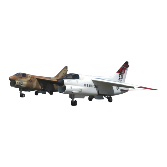
Page 38: Edwards Air Force Base A-7D
JHI-A7-06-0001 Edwards Air Force Base A-7D Have questions? Call us at 562-467-0260 or email larrywjhi@jethangar.com... - Page 39 JHI-A7-06-0001 Have questions? Call us at 562-467-0260 or email larrywjhi@jethangar.com...
-
Page 40: Desert Storm Cag A-7E
JHI-A7-06-0001 VA-72 Desert Storm CAG A-7E Have questions? Call us at 562-467-0260 or email larrywjhi@jethangar.com... - Page 41 JHI-A7-06-0001 Have questions? Call us at 562-467-0260 or email larrywjhi@jethangar.com...
-
Page 42: Appendix B: Cockpit Diagrams
JHI-A7-06-0001 APPENDIX B: Cockpit Diagrams Have questions? Call us at 562-467-0260 or email larrywjhi@jethangar.com... -
Page 43: Assembly Notes
JHI-A7-06-0001 Assembly Notes The following represents the plans for building of the cockpit kit. The cockpit kit is made of vacuum formed plastic which can be assembled using any of the various types of CA glues or epoxy. Color notes as well as picture references are provided for your convenience. -
Page 44: Assembly Drawings
JHI-A7-06-0001 Assembly Drawings Have questions? Call us at 562-467-0260 or email larrywjhi@jethangar.com... - Page 45 JHI-A7-06-0001 Have questions? Call us at 562-467-0260 or email larrywjhi@jethangar.com...
- Page 46 JHI-A7-06-0001 Have questions? Call us at 562-467-0260 or email larrywjhi@jethangar.com...
- Page 47 JHI-A7-06-0001 Have questions? Call us at 562-467-0260 or email larrywjhi@jethangar.com...
- Page 48 JHI-A7-06-0001 Have questions? Call us at 562-467-0260 or email larrywjhi@jethangar.com...
-
Page 49: Cockpit References
JHI-A7-06-0001 Cockpit References Have questions? Call us at 562-467-0260 or email larrywjhi@jethangar.com... - Page 50 JHI-A7-06-0001 Have questions? Call us at 562-467-0260 or email larrywjhi@jethangar.com...
-
Page 51: Appendix C: Weapons Pylons Installation Drawings
JHI-A7-06-0001 APPENDIX C: Weapons Pylons Installation Drawings Have questions? Call us at 562-467-0260 or email larrywjhi@jethangar.com... -
Page 52: Assembly Notes
JHI-A7-06-0001 Assembly Notes The weapons pylons are included with this kit as an added feature for the scale enthusiast. The A-7 full sized aircraft rarely flew without pylons, so why should the model? The installation is simple as hardpoints are already installed in the wing and the parts are included with the kit. -
Page 53: Assembly Drawings
JHI-A7-06-0001 Assembly Drawings Have questions? Call us at 562-467-0260 or email larrywjhi@jethangar.com... - Page 54 JHI-A7-06-0001 Have questions? Call us at 562-467-0260 or email larrywjhi@jethangar.com...
- Page 55 JHI-A7-06-0001 Have questions? Call us at 562-467-0260 or email larrywjhi@jethangar.com...
-
Page 56: Appendix D: Landing Gear Scale Details
JHI-A7-06-0001 APPENDIX D: Landing Gear Scale Details Have questions? Call us at 562-467-0260 or email larrywjhi@jethangar.com... -
Page 57: Notes
JHI-A7-06-0001 Notes These are some simple scale details that can be added to the aircraft wheels which help enhance the scale looks of this aircraft. You will be surprised at the difference it makes in appearance! Have questions? Call us at 562-467-0260 or email larrywjhi@jethangar.com... -
Page 58: Nose Gear
JHI-A7-06-0001 Nose Gear Using the pattern below, cut two each wheel hubs out of 1/64” plywood. For drilling the holes, the use of a sharpened brass tube is recommended. Glue the wheel hub onto the tire with thin CA. Mask and paint the wheel hub white. Remove the wheel axle from the nose strut and cut it in half using a Dremel cutoff wheel. -
Page 59: Main Gear
JHI-A7-06-0001 Main Gear Disassemble the Robart wheels. Paint the rear wheel hub white and the front wheel hub black. Drill out the center of the Robart wheel cover and paint it white. Paint the center hub black. Slim down two 3/16” wheel collars. Note: This can be using a bench sander/grinder or using a dremel cutoff wheel. -
Page 60: Appendix E: Arf A-7 Corsair Ii Plans
JHI-A7-06-0001 APPENDIX E: ARF A-7 Corsair II Plans Have questions? Call us at 562-467-0260 or email larrywjhi@jethangar.com... - Page 61 JHI-A7-06-0001 Have questions? Call us at 562-467-0260 or email larrywjhi@jethangar.com...
- Page 62 JHI-A7-06-0001 Have questions? Call us at 562-467-0260 or email larrywjhi@jethangar.com...
- Page 63 JHI-A7-06-0001 Have questions? Call us at 562-467-0260 or email larrywjhi@jethangar.com...
- Page 64 JHI-A7-06-0001 Have questions? Call us at 562-467-0260 or email larrywjhi@jethangar.com...
- Page 65 JHI-A7-06-0001 Have questions? Call us at 562-467-0260 or email larrywjhi@jethangar.com...
- Page 66 JHI-A7-06-0001 Have questions? Call us at 562-467-0260 or email larrywjhi@jethangar.com...
Need help?
Do you have a question about the A-7D/E Corsair II and is the answer not in the manual?
Questions and answers