Table of Contents
Advertisement
Quick Links
Model 8210A-2-5
Operation & Installation Manual
SmartStep
Aeroflex / Weinschel
Manual Rev. 01-10
Firmware Version 1.00
Programmable Attenuator/Switch Controller
(Model 8210A-2-5)
This documentation may not be reproduced in any form, for any
purpose unless authorized in writing by Aeroflex / Weinschel, Inc.
© Aeroflex / Weinschel, Inc.
Frederick, Maryland
2003 - 2010
IM-377
IM-377
1
Advertisement
Table of Contents

Summary of Contents for Aeroflex SmartStep 8210A-2-5
- Page 1 SmartStep Programmable Attenuator/Switch Controller (Model 8210A-2-5) This documentation may not be reproduced in any form, for any purpose unless authorized in writing by Aeroflex / Weinschel, Inc. © Aeroflex / Weinschel, Inc. Frederick, Maryland 2003 - 2010 Aeroflex / Weinschel Manual Rev.
-
Page 2: Table Of Contents
6. DEVICE INTERFACE BUS (DIB) ............................15 6-1. GENERAL OPERATION ................................15 6-2. DIB CONNECTOR ..................................16 7. CONFIGURING & USING THE 8210A-2-5 ........................17 7-1. MANUFACTURING SELECT SWITCH SW3 ..........................17 7-2. CONFIGURATION FUNDAMENTALS ............................17 7-3. DEVICE PROTOCOLS ................................17-18 7-4. - Page 3 EXAMPLE 9: USING MACROS TO SIMPLIFY PROGRAMMING MULTIPLE RF SWITCHES ............. 49 10. MAINTENANCE ................................. 50 11. APPLICATIONS .................................. 50 12. ACCESSORIES .................................. 50 13. CONTACTINGAEROFLEX / WEINSCHEL ........................51 14. AEROFLEX / WEINSCHEL WARRANTY ........................51 Aeroflex / Weinschel...
-
Page 4: General Information
I C serial bus and several software protocol layers that allow the Model 8210A-2-5 to address up to 125 peripheral devices, with serial data rates of up to 100 KHz. The DIB may also be used to supply DC power to the devices, resulting in a simple, low-cost interconnection system. -
Page 5: Unpacking And Inspection
1-6. STORAGE: Storage of the Model 8210A-2-5 SmartStep™ Programmable Attenuator/Switch Controller is possible for extended periods without incurring damage to internal circuitry if the 8210A-2-5 Series is packaged according to the instructions above. The safe limits for storage environment are as follows: Temperature: 67°... -
Page 6: Related Manuals
Device Interface Bus To Be Determined 1-10. SAFETY CONSIDERATIONS: The Model 8210A-2-5 Programmable Attenuator/Switch Controller and all related documentation must be reviewed for familiarization with safety markings and procedures before any operation and/or service. Refer to the SAFETY SUMMARY located at the beginning of this manual for a summary of safety information and procedures. -
Page 7: Specifications
Model 8210A-2-5 IM-377 2. SPECIFICATIONS: 2.5mm barrel style Connector: DC Input +5 Vdc @ 375 mA Requirements: 14-pin 0.025" square post header @ 0.1" Driver Interface Connector: centers. Mates with AMP 746285-2 or equivalent. serial data Signals : serial clock... -
Page 8: Physical Dimensions
Model 8210A-2-5 IM-377 3. PHYSICAL DIMENSIONS: Note: All dimensions are given in mm (inches) and are maximum, unless specified. Aeroflex / Weinschel... -
Page 9: Installation
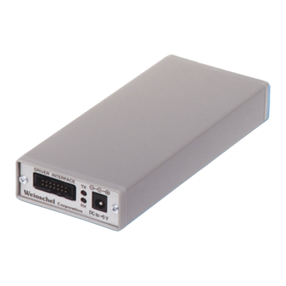
8210A-2-5. d. Connect a +5 V Power Supply to the Model 8210A-2-5’s DC IN +5V Input Connector which is located on the Model 8210A-2-5 front panel (Figure 1), is a standard 2.5mm barrel style DC jack. Refer to specifications for exact power requirements. -
Page 10: Serial Communications Settings
Model 8210A-2-5 IM-377 5. SERIAL (RS-232, RS-232 & RS-485) OPERATION: 5-1. SERIAL COMMUNICATIONS SETTINGS: The Serial Communications options are programmed via an internal 8 position DIP switch SW1 which is located on the rear panel. The switch is shared between the two functions, with SW1-1 controlling the selection. -
Page 11: Serial (Rs-232, Rs-422 & Rs-488) Operation
2400, 9600, 19200, or 34800. Parity selections include settings for None, Even, or Odd parity. Handshaking may be enabled, if desired, and the method may be set to either hardware (RTS/CTS) or software (XON/XOFF). For interactive terminal use, echoing may be enabled, in which the 8210A-2-5 will echo all characters received back to the terminal. - Page 12 RTS signal. In addition, the 8210A-2-5 unasserts the RTS signal while command execution is in progress. For those systems incorporating local front panel controls, the serial port can lockout local users, providing a Remote/ Local function similar to that of GPIB operation.
-
Page 13: Rs-232 Operation
5-3. RS-232 Operation: The RS-232 Serial port is a 9-pin connector that is compatible with the pin-out of the serial port on a PC. It allows the use of a null-modem style cable. The pin-out for the connector is show below. For clarity, the signal names and directions are relative to the 8210A-2-5. Signal Name... -
Page 14: Rs-422/Rs-488 Operation
Model 8210A-2-5 IM-377 5-4. RS-422/RS485 OPERATION: The RS422/RS485 Serial mode is useful in applications requiring long cable lengths (up to5000 ft at 9600 baud), or in electrically noisy environments. All communication parameters available for the RS232 port are available under RS422 operation (baud rate, handshaking, etc). Full Duplex operation is supported. -
Page 15: Device Interface Bus (Dib)
By similar devices providing a consistent API to the 8210A-2-5, the user is freed from the concerns of the low-level programming required to control each device. -
Page 16: Dib Connector
IM-377 6-2. DIB CONNECTOR. This connector (shown below) is a 14-pin 0.025" square post header @ 0.1" centers and is located on the front panel of the Model 8210A-2-5 and mates with AMP connector P/N 746285-2 or equivalent. Name Description... -
Page 17: Configuring & Using The 8210A-2-5
The 8210A-2-5 provides a much simpler and easier method - assigning a name to a device. The 8210A-2-5 allows the user to assign an alphanumeric name of up to 10 characters in length to a device, and can store this association in it’s non-volatile EEPROM memory for future use. -
Page 18: The Virtual Attenuator
The 8210A-2-5 provides a solution to this dilemma with the ability to create and define a virtual device. A virtual device allows the user to construct a device by combining the attributes of several physical devices, and be able to program this combination as if it were one physical device! Revisiting our example above, we can create a virtual attenuator with an attenuation range of 81dB/1dBsteps, effectively creating a "150T-81". -
Page 19: The Virtual Switch
1, 2, or3 when programming. The 8210A-2-5 supports up to 32 Virtual Switch devices, each of which can support up to a maximum of 16 output signals. The Virtual Switch uses the Switch Protocol command set. During the setup process, the user assigns a name to the virtual switch, which may be stored in the 8210A-2-5’s non-volatile EEPROM memory for future use. -
Page 20: General Syntax Structure
STB serves no purpose. 7-8. GENERAL SYNTAX STRUCTURE: The following paragraphs outline the general syntax and command structure for the Model 8210A-2-5. This structure is common to all bus flavors of the Model 8210A-2-5. NOTE In the descriptions that follow, the term whitespace is used to define a sequence of one or more combinations of ASCII Space (20h), Carriage return (0Dh), or Tab (09h) characters. -
Page 21: 7-8.2. Syntax Of Commands
If multiple commands are made on the same program line, separate the individual command messages with a semicolon. Arguments - The 8210A-2-5 supports a variety of argument types that can be used in program commands. These types are: ... -
Page 22: 7-8.3. Output Data Format
Model 8210A-2-5 IM-377 7-8.3 OUTPUT DATA FORMAT. Output data from the Model 8210A-2-5 consists of a series of ASCII digits and message strings, terminated with an ASCII Line-Feed character (0AH), in response to a program message that contains one or more query commands. In the case of multiple query commands in the same program message, the data resulting from each of the individual message units will be separated by an ASCII comma (2CH) character. -
Page 23: 488.2 Common Commands
This function is used to read the system identification information, which is a string consisting of the Remarks: following data: manufacturer, model, serial number, and firmware version. mfg integer count of devices Return Value: *IDN? returns the following ’Weinschel,8210A-2-5 Series, 123, 1.00A’ Example(s): Aeroflex / Weinschel... - Page 24 Model 8210A-2-5 IM-377 Performs a device reset. *RST Function: *RST Syntax: none Argument(s): This function is used to reset the device. Remarks: none Return Value: *RST Example(s): Operation complete service request. *OPC Function: *OPC Syntax: none Argument(s): This function generates the Operation Complete message (OPC) in the Standard Event Status Remarks: Register when all pending device operations have finished.
-
Page 25: Device Assignment & Configuration Commands
Specifying a serialno of -1 will allow the 8210A-2-5 to match any device of the appropriate model, however, use this feature with caution, since a system containing multiple instances of the same model will fail to configure appropriately. - Page 26 ASSIGN command. If the device does not have an assigned name, then the string NONAME is returned in this field. The model and id fields are read from the device, and the addr field is the Device Interface Bus address assigned by the 8210A-2-5 configuration process. Return Value:...
- Page 27 Model 8210A-2-5 IM-377 ADDR? Function: Reads the Device Interface Bus address assigned to a device. Syntax: This command has two forms: ADDR? devname ADDR? model id Argument(s): devname string10 assigned device name model string8 device model integer32 device serial number/id...
-
Page 28: Attenuator Assignment Commands
Model 8210A-2-5 IM-377 7-11. Attenuator Assignment ASSIGN ATTN Function: Assign a virtual attenuator Syntax: ASSIGN ATTN name devname [devname [devname [devname]]] Argument(s): name string10 virtual attenuator name devname string10 device name(s). see remarks. Remarks: This function is used to assign a user-definable name and configuration to a virtual attenuator. -
Page 29: Attenuator Control Commands
Model 8210A-2-5 IM-377 7-12. Attenuator Control ATTN Function: Set attenuation Syntax: ATTN name atten (specific form) or ATTN atten (non-specific form) Argument(s): name string10 attenuator or group name atten real desired value, in dB Remarks: This function sets the attenuation of attenuator name to atten. This command may be used with both physical and virtual attenuation devices supporting the AttnProtocol. - Page 30 Model 8210A-2-5 IM-377 RELATTN? Function: Read relative attenuation Syntax: RELATTN? name Argument(s): name string10 attenuator name Remarks: This function reads the relative attenuation of attenuator name. This command may be used with both physical and virtual attenuation devices supporting the AttnProtocol. The parameter name must have been previously assigned using either the ASSIGN or ASSIGN ATTN command.
- Page 31 Model 8210A-2-5 IM-377 ATTN? GETCAP Function: Reads the capability of an attenuator Syntax: ATTN? GETCAP name Argument(s): name string10 attenuator name Remarks: This function reads the capability information of attenuator name. This command may be used with both physical and virtual attenuation devices supporting the AttnProtocol. The parameter name must have been previously assigned using either the ASSIGN or ASSIGN ATTN command.
-
Page 32: Switch Assignment Commands
Model 8210A-2-5 IM-377 7-13. Switch Assignment ASSIGN SWITCH Function: Assign a virtual switch Syntax: ASSIGN SWITCH name devname mask mode Argument(s): name string10 virtual switch name devname string10 device name mask integer16 output mask mode integer operational mode (0=Encoded, 1=Decoded) -
Page 33: Switch Control Commands
Model 8210A-2-5 IM-377 7-14. Switch Control SWITCH Function: Set switch value Syntax: SWITCH name setting (specific form) or SWITCH setting (non-specific form) Argument(s): name string10 switch name setting integer16 desired switch setting Remarks: This function sets the outputs of switch name to setting. This command may be used with both physical and virtual switch devices supporting the SwitchProtocol. -
Page 34: Group Assignment Commands
Model 8210A-2-5 IM-377 7-15. Group Assignment GROUP Function: Assign a group of attenuators Syntax: GROUP groupname attnname [attnname…] Argument(s): groupname string10 group name attnname string10 attenuator name(s). see remarks. Remarks: This function is used to assign a user-definable name and configuration to a group. -
Page 35: Macro Commands
Model 8210A-2-5 IM-377 7-16. Macro Commands MACRO Function: Define a macro Syntax: MACRO name text Argument(s): name string10 macro name text string macro body Remarks: This function is used to define a macro. The macro name may be any user-defined string, and may also be the same as internal commands. -
Page 36: Memory Commands
Model 8210A-2-5 IM-377 7-17. Memory Commands DELETE Function: Deletes an assigned device name, virtual attenuator, virtual switch, group, or macro Syntax: DELETE ASSIGN name Deletes an assigned device name DELETE ASSIGN ATTN name Deletes an assigned virtual attenuator name DELETE ASSIGN SWITCH name... -
Page 37: Misc Commands
GPIB REMOTE/LOCAL/LOCAL LOCKOUT functionality. When lockout is in effect, the front panel REM indicator will be illuminated, indicating to the local user that the 8210A-2-5 is under remote control. The value of setting controls the function as follows:... -
Page 38: Device Interface Bus Control Commands
This function is used to set the output formatting style used for hex numbers. By default, the 8210A-2-5 uses the formatting prefix specified by IEEE 488.2, which uses a prefix of ’#H’ for hex numbers. If desired, this prefix may be changed to the C language style "0X" by specifying a value of 0 for the fmt argument. -
Page 39: Base Protocol Commands
Model 8210A-2-5 IM-377 7-20. Base Protocol Commands DEVICE RESET Function: Sends a Reset msg to the device Syntax: DEVICE RESET addr Argument(s): Arguaddr integer address Remarks: This function is used to send a Reset msg to the speci Return Value:... -
Page 40: Step Attenuator Protocol Commands
Model 8210A-2-5 IM-377 7-21. Step Attenuator Protocol Commands DEVICE ATTN Function: Sets the attenuation of a device Syntax: DEVICE ATTN addr atten Argument(s): addr integer address atten unit attenuation, scaled to 0.01 (ie INT(A*100)) Remarks: This function is used to set the attenuation of a device. The atten parameter is an integer representation of the desired attenuation, scaled by a factor of 100 (ie the protocol supports a resolution of 0.01dB). - Page 41 Model 8210A-2-5 IM-377 DEVICE? READ COUNTER Function: Reads the cycle counter for the specified relay cell Syntax: DEVICE? READ COUNTER addr cellno Argument(s): addr integer address relay byte relay # (1-8) Remarks: This function is used to read the setting of the device’s relay switching counter, which records the total number of switching cycles the cell has performed since mfg.
-
Page 42: Switch Protocol Commands
Model 8210A-2-5 IM-377 7-22. Switch Protocol Commands DEVICE SET Function: Sets the output of a device Syntax: DEVICE SET addr setting Argument(s): addr integer address setting word output setting Remarks: This function is used set the output of a device. -
Page 43: Programming And Configuration Examples
Example 1: Single Attenuator If there is only one attenuator connected to the 8210A-2-5, then the assignment of a device name is not required, and operation couldn’t be simpler. You can just send attenuation commands and queries, ignoring the device name parameter. -
Page 44: Example 3: Vrtual Attenuator
Model 8210A-2-5 IM-377 Example 3: Virtual Attenuator In this example, we will use two attenuators to create a virtual attenuator. We will use a Model 150T-70 (70dB/10dB steps) serial number 101, and a Model 150T-11 (11dB/1dB steps) serial number 102, to create a virtual attenuator with an 81dB (70+11) range, in 1dB steps. -
Page 45: Example 4: Attenuator Groups
Model 8210A-2-5 IM-377 Example 4: Attenuator Groups In this example, we will use four attenuators to create an attenuator group. We will use the following devices: Attenuator #1: Model 3200T-1, serial number 101 Attenuator #2: Model 3200T-1, serial number 102... -
Page 46: Example 5: Multiple Virtual Attenuators With Group
Model 8210A-2-5 IM-377 Example 5: Multiple Virtual Attenuators with Groups In this example, we will use eight attenuators to create four virtual attenuators, and then assign these to two different groups. The virtual attenuators will each be comprised of a Model 3200T-1 (127dB/1dB steps) and a Model 3201T-4 (1.2dB/0.1dB steps) to create a virtual 128.2dB/0.1dB step attenuator... -
Page 47: Example 6: Single Spdt Switch
Model 8210A-2-5 IM-377 Example 6: Single SPDT Switch This example shows using the Relay Output Card (Model 193-8015) to control a SPDT RF switch (failsafe type). Typically, a SPDT switch requires 1 control line to set the state of the switch, and the switch has two states: 0 (off, or NC), and 1 (on, or NO). -
Page 48: Example 8: Multiple Sp4T Switches (Virtual Switch)
Model 8210A-2-5 IM-377 Example 8: Multiple SP4T Switches (Virtual Switch) This example shows using the Relay Output Card (Model 193-8015) to control two SP4T RF switches (failsafe type). Typically, a SP4T switch requires 4 control lines to set the state of the switch, and the switch has 5 states: 0 ( all off), and position 1 thru position 4. -
Page 49: Example 9: Using Macros To Simplify Programming Multiple Rf Switches
Model 8210A-2-5 IM-377 Example 9: Using macros to simplify programming multiple RF Switches This example shows how using macros can simplify the programming of large switching matrices. In order to simplify the example, we will only use 3 SPDT switches. Assume that the switches are arranged in a tree fashion, with the two outputs of SW1 connected to the inputs of SW2 and SW3, respectively, creating 4 output paths from switches SW2 and SW3. -
Page 50: Maintenance
Applications for the 8210A-2-5 range from providing control of a single SmartStep Attenuator in a bench test/lab environment using a PC and a terminal emulator, to complex system applications where the 8210A-2-5 is employed to control many devices to create custom/semi-custom subsystems to reduce overall design cost. -
Page 51: Contactingaeroflex / Weinschel
Aeroflex / Weinschel by the original purchaser within ONE YEAR from the date of shipment. The foregoing Warranty does not apply Aeroflex / Weinschel, Inc.’s sole opinion to products that have been subject to improper or inadequate maintenance, unauthorized modifications, misuse, or operation outside the environmental specifications for the product. - Page 53 PROG BASE GETCAP VALUE PROTOCOL BUILD GETID PWRONSETTING BUFFER GPIB READ CHANNEL abbr CHAN) GROUP REASSIGN CELL REBOOT CMDSET RECALL COMM IDWAIT RECONFIG CONFIG (abbr CFG) COUNT (abbr CNT) INCR RELATTN COUNTER INPORT? COUNTERS IOMODE Revised 8-30-03 Aeroflex / Weinschel...
- Page 54 Additional status data structures used in status reporting none 22 Commands overlapped/sequential. All commands are sequential Functional criteria met with an operation complete Command is finish executing message is generated in response to that command Revised 8-30-03 Aeroflex / Weinschel...
- Page 55 Model 8210A-2-5 (IM-355) Revision Record APPLICABLE REVISION DATE DESCRIPTION SERIAL NUMBERS 9/03 Initial Issue All Units 4/04 Company Name change to Aeroflex / Weinschel. All Units 1/10 Corrected callout error on page 16 from +15 V to +5 V All Units...
-
Page 56: Ec Declaration Of Conformity
EC DECLARATION OF CONFORMITY This is to certify that the: SmartStep Programmable Attenuator & Controller 3200T-2 & 8210A-1/2 Manufactured by: Weinschel Corporation Conforms with the protection requirements of Council Directive 89/336/EEC and the Amending Directive 93/68/EEC, relating to Electromagnetic Compatibility, by the application of: EN50081-1: 1992 Generic Emissions Standard.
Need help?
Do you have a question about the SmartStep 8210A-2-5 and is the answer not in the manual?
Questions and answers