Table of Contents
Advertisement
Advertisement
Table of Contents

Related Manuals for Shenzhen mindray PM 50


Summary of Contents for Shenzhen mindray PM 50
- Page 1 PM-50 Pulse Oximeter Operation Manual...
- Page 3 Copyright © SHENZHEN MINDRAY BIO-MEDICAL ELECTRONICS CO., LTD. Version: 1.0 Issued Date: December 20, 2004 ALL RIGHTS RESERVED. Statement SHENZHEN MINDRAY BIO-MEDICAL ELECTRONICS CO., LTD. (hereinafter called Mindray) owns all rights to this published work and intends to maintain this work as confidential. Mindray may also seek to maintain this work as an unpublished copyright.
- Page 4 Content of this manual is subject to change without prior notice. Trademark is Mindray’s trademark. Mindray states that other trademarks that appear in this manual are used only for editorial purpose and to the benefit of the trademark owner with no intention of improperly using. Responsibility of the Manufacturer Mindray is responsible for the safety, reliability, and performance of the referenced equipment only under the following conditions:...
- Page 5 Warranty THIS WARRANTY IS EXCLUSIVE AND IS IN LIEU OF ALL OTHER WARRANTIES, EXPRESSED OR IMPLIED, INCLUDING WARRANTIES OF MERCHANT ABILITY OR FITNESS FOR ANY PARTICULAR PURPOSE. Exemptions Mindray's obligation or liability under this warranty does not include any transportation or other charges, or liability for direct, indirect or conseq- uential damages or delay resulting from the improper use or application of the product, or the substitution of parts or accessories not approved by Mindray, or repairs performed by anyone other than a Mindray...
- Page 6 Return Policy In the event that it becomes necessary to return a unit to Mindray, follow the instructions below. 1. Obtain a return authorization. Contact Mindray to obtain a Customer Service Authorization number. This number must be marked clearly on the outside of the shipping container.
-
Page 7: Safety Symbols
Safety Symbols Warning A Warning indicates that failure to follow proper instructions can cause death or injury to the patient, the operator, or serious damage to the equipment. Caution A Caution indicates that failure to follow proper instructions may cause serious injury to the patient, the operator, or may cause damage to the equipment. -
Page 9: Table Of Contents
Contents Contents Charpter 1 Safety Information............1 Charpter 2 General ................3 2.1 Introduction ................3 2.2 Functions ................3 2.3 Appearance ................4 2.4 Displayed Information ............. 5 2.5 Button Operation ..............6 2.5.1 Power Button ..............6 2.5.2 Backlight Button ............6 2.5.3 Confirm ID Button ............ - Page 10 Contents 5.1.2 Data Adding ..............21 5.1.3 Data Protection ............21 5.1.4 Data Deletion .............. 22 5.2 Messages Prompting ............23 5.3 Power Management .............. 25 Charpter 6 Maintenance ..............26 6.1 System Check ............... 26 6.2 General Cleaning ..............27 6.3 Sterilization/Disinfection ............
-
Page 11: Charpter 1 Safety Information
Safety Information Charpter 1 Safety Information This chapter contains important safety information related to general use of the PM-50 Pulse Oximeter (hereinafter referred to as the PM-50). Other important safety information appears throughout the manual in sections that relate specifically to the precautionary information. Note Important! Before use, carefully read this manual, all safety information and specifications. - Page 12 Safety Information To avoid fire or explosion hazards, do not use the PM-50 at places where such flammable material as anaesthesia gas is present. Do not pull or lift the PM-50 by its connection cable. That may lead to device falling and consequent patient injuries. It is not recommended to hang the PM-50 when transporting patients.
-
Page 13: Charpter 2 General
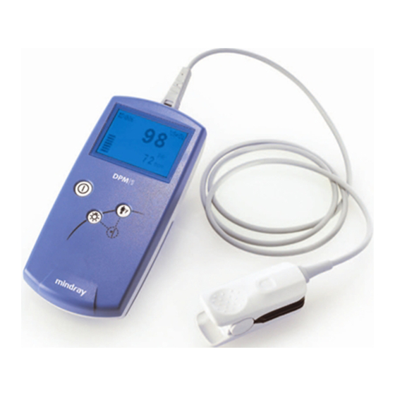
General Charpter 2 General 2.1 Introduction The PM-50 pulse oximeter is a portable measuring device powered by common or rechargeable batteries. It is compact, light, flexible to use and easy to learn. Parameters measured by the PM-50 include: arterial oxygen saturation (SpO ), pulse rate (PR) and pulse strength. -
Page 14: Appearance
General 2.3 Appearance Figure 2-1 Front Panel Figure 2-2 Back Panel Table 2-1 Appearance description Description Remarks Dual-purpose It connects SpO2 sensor or PC communication cable. socket It displays information listed in Table 2-2. Power It turns on or off the device. Confirm ID It confirms the patient ID for current measurement. -
Page 15: Displayed Information
General 2.4 Displayed Information Figure 2-3 shows information displayed on the PM-50’s screen. Figure 2-3 Displayed Information Table 2-2 Description of displayed information Description Remarks ID number It displays current ID number ranging from 000 to 100 ID Full It appears when ID 95 and blinks when stored ID is being covered by new ID. -
Page 16: Button Operation
General 2.5 Button Operation Three soft buttons are available on the PM-50’s front panel. Power Backlight Confirm ID Figure 2-4 Buttons 2.5.1 Power Button Power-on: Press to turn on the device. Power-off: Press and hold for two seconds to turn off the device. Note The PM-50 is powered by batteries only. -
Page 17: Confirm Id Button
General 2.5.3 Confirm ID Button The Confirm ID button is used to add data. It enables the user to add data, without using a new ID number, to a re-test for the same patient after the sensor is accidentally disconnected. Refer to section 5.1 Data Management for detailed use of this button. -
Page 18: Charpter 3 Installation
Installation Charpter 3 Installation 3.1 Unpacking and Inspection Please carefully remove the PM-50 and its accessories from the package and check items by comparing them to the packing list. Check the device for any mechanical damages. Check all cables and accessories for damage. In case of any problem, please contact Mindray Customer Service. - Page 19 Installation shown in Figure 3-2. 5. Push the door back. Note Before disposing of the battery, check with your local solid waste officials for details in your area for recycling options or proper disposal. Caution Please use AA alkaline batteries or rechargeable batteries. Do not use carbon or poor quality batteries.
-
Page 20: Power-On
Installation 3.3 Power-on Press the Power button to turn on the device. The following startup interfaces will be displayed. Figure 3-3 Startup interface 1 Figure 3-4 Startup interface 2 Figure 3-3 shows Mindray’s logo. Figure 3-4 shows the product name and software version. -
Page 21: Connect Computer
Installation Figure 3-7 Connect SpO sensor 3.4 Connect Computer The PM-50 can be connected to a Personal Computer through a communication cable to transmit patient’s trend to the computer for printing. Simply connecting one end of the PC communication cable to the PM-50’s dual-purpose socket and the other end to the PC’s serial port. -
Page 22: Charpter 4 Measurement
Measurement Charpter 4 Measurement 4.1 Measuring Principle The PM-50 Pulse Oximeter is capable of measuring SpO , PR and pulse strength. The PM-50 measures SpO by a method called pulse oximetry. It is a continuous, non-invasive method based on the different absorption spectra of reduced hemoglobin and oxyhemoglobin. -
Page 23: Precautions
Measurement 4.2 Precautions Note Do not perform SpO monitoring and NIBP measurements on the same arm simultaneously. Obstruction of blood flow during NIBP measurements may adversely affect the reading of the SpO value. It is recommended that each measurement last longer than 15 seconds. - Page 24 Measurement Do not reuse disposable SpO sensors. Prolonged and continuous monitoring may increase the risk of burns at the site of the sensor. If you have to use the PM-50 for Prolonged and continuous monitoring, it is especially important to check the sensor placement, and ensure proper attachment on neonates and patients of poor perfusion or skin sensitive to light.
-
Page 25: Measuring Steps
Measurement 4.3 Measuring Steps The measurement is usually done using the adult finger SpO sensor. Palm or foot sensors may be adopted for infants. Before measurement, check the SpO sensor and its cable for damages. Do not use the sensors if any damage is found. 4.3.1 Adult Measurement Please follow the steps below to use the adult finger SpO sensor:... -
Page 26: Neonatal Measurement
Measurement 4.3.2 Neonatal Measurement Please follow the steps below to use the neonatal SpO sensor: Insert the SpO sensor‘s connector into the PM-50’s dual-purpose socket. Turn on the PM-50 to enter the standby mode. Appropriately place the neonatal SpO sensor (refer to 4.3.3 Placing Neonatal SpO sensor). - Page 27 Measurement Figure 4-3 Placing Neonatal SpO Sensor 2 Figure 4-3 shows the neonate SpO2 sensor after insertion. Wind the SpO sensor around a hand or foot. Hold the sensor, pull the belt and fit one of its sides with “V” edge into the “V” groove on the corresponding side of the sheath.
-
Page 28: Measuring Restrictions
Measurement Figure 4-4 Placing Neonatal SpO Sensor 3 4.4 Measuring Restrictions If the accuracy of any measurement seems unreasonable, first check the patient’s vital signs by an alternate method, and then check the device for proper function. Inaccurate measurements may be caused by the following reasons. Incorrect sensor application or use;... - Page 29 Measurement Placement of a sensor on the same extremity with a blood pressure cuff, arterial catheter, or intravascular line. Loss of pulse signal can occur in the following situation: The sensor is too tight; There is excessive illumination from light sources such as a surgical lamp, a bilirubin lamp, or sunlight;...
-
Page 30: Charpter 5 Other Functions
Other Functions Charpter 5 Other Functions 5.1 Data Management 5.1.1 Data Storage The PM-50 oxidmeter has its internal memory to store data. The memory is divided into the ID Data Zone and Trend Data Zone. The ID Data Zone is capable of storing 100 patients’ ID data at most. When the number exceeds 100, new data will automatically cover the old one from the earliest stored data. -
Page 31: Data Adding
Other Functions The first trend data will be stored 15 seconds after the pulse is found. Thereafter one trend data will be stored every 2 minutes. One trend data includes: Average SpO value within the measuring period. Average PR value within the measuring period. 5.1.2 Data Adding The previously stored ID number appears on the screen when a finger is inserted into the SpO... -
Page 32: Data Deletion
Other Functions 5.1.4 Data Deletion Press the Delete ID button in the standby mode, the message “DELETE ALL?” will be displayed as shown in figure 5-1. Figure 5-1 Delete data1 Figure 5-2 Delete data2 To delete all stored data: Press the Delete ID button again. As shown in figure 5-2, the message “ALL DELETED”... -
Page 33: Messages Prompting
Other Functions 5.2 Messages Prompting The PM-50 can display various prompt messages. In table 5-1, prompt messages as well as their causes and solutions are listed. Table 5-1 Table of Indications Message Cause Solution Batteries energy lower “Low Battery” Replace batteries in time than 4.0 Voltage. - Page 34 Other Functions The PM-50 can also display technical error messages. In table 5-2, error messages as well as their causes and solutions are listed. If the LCD screen can’t display anything, it may be damaged or error occurs during system self-test. Please shut down the device (if can’t, remove the batteries) and contact Mindray Customer Service.
-
Page 35: Power Management
Other Functions 5.3 Power Management Battery Detection The PM-50 can detect the battery energy and display message when battery voltage is less “Low Battery” than 4.0 V; shut down the device automatically when battery voltage is less than 3.85V. Energy Saving The PM-50 can save the energy of the batteries by switching to the standby mode automatically when the finger disconnects from the sensor or the sensor disconnects from... -
Page 36: Charpter 6 Maintenance
Maintenance Charpter 6 Maintenance 6.1 System Check Before using the PM-50, perform the following steps. Check for any mechanic damages. Check for all cables and accessories for damage. Check all functions of the PM-50 to make sure the PM-50 is in proper working condition. -
Page 37: General Cleaning
Maintenance 6.2 General Cleaning The PM-50 must be kept dust-free. Regular cleaning (depending on the policy of your institution) of its exterior surface and LCD screen is strongly recommended. First absorb non-corrosive detergent with clean and soft cloth or cotton ball. Manually twist the cloth or cotton ball to a proper degree and then use the dried cloth or cotton ball for cleaning. -
Page 38: Sterilization/Disinfection
Maintenance Caution Do not use ammonia-based or acetone-based cleaners such as acetone. Most detergents must be diluted before use. Please follow the manufacturer’s directions carefully. Do not use abrasive material, such as steel wool. Do not allow any liquid inside the device. Do not immerse the device into any liquid. -
Page 39: Disposal
Maintenance in the Hospital Maintenance Schedule. Cleaning is recommended before sterilization or disinfection. Recommended disinfection materials: ethylate, and acetaldehyde. The SpO cable can be cleaned with 3% hydrogen peroxide solution or 70% isopropanol solution. Active reagents are also effective for this purpose. -
Page 40: Charpter 7 Pm-50 Management System
PM-50 Management System Charpter 7 PM-50 Management System The PM-50 Management System (PMS) is developed to realize more functions of the PM-50. The PM-50 Management System runs in Windows 98/2000/XP operation system. In conjunction with the internal software of the PM-50, the following functions can be realized. Outputting data and upgrading internal software. -
Page 41: Uninstall
PM-50 Management System your PC, and click “Next” to resume. Choose the destination folder where the PM-50 Management System is to be installed. Click “Next” and “Finish” according to the prompt. After the installation is completed, a new shortcut icon will appear in the desktop of your computer as shown below. -
Page 42: Main Interface
PM-50 Management System 7.2 Main Interface Double clicking the shortcut icon for PM-50 Management System on the desktop of your computer, the Main Interface of PM-50 Management System will be displayed as shown in Figure 7-1. Figure 7-1 Main Interface Menu Bar Tool Bar Data Area... - Page 43 PM-50 Management System <File> Click the <File> menu to see its pull-down menu as show in Figure 7-2. There are five submenus: <File Management>: Click to open the “File Management” dialogue box. <Print>: Click to print the current patient data. <Print Preview>: Click to preview the data to be printed.
- Page 44 PM-50 Management System When you use the Data Output or Software Upgrade function, the default serial port might have been occupied. At this time, you can click the <Serial Port Selection> menu to select other serial port. <Operation> Click the <Operation> menu to see its pull-down menu as show in Figure 7-4.
-
Page 45: Tool Bar
PM-50 Management System <Help>: Click to open the “Help” document. <About PMS>: Click to show the copyright information. Note When you open the “Help” document, if a dialog box pops up and informs you to install language pack, please select “Never install any language packs”, and then click “Cancel”... -
Page 46: Functions
PM-50 Management System It displays the patient Name, Sex, Age, and Doctor etc. Patient Data Area It displays the value of the measured SpO and PR as well as the corresponding Index No and Save Time of each measurement. The data displayed as “---” is invalid. The content in the Information Area can’t be directly inputted or changed. - Page 47 PM-50 Management System Figure 7-7 Save the Outputted File You can choose the file directory where the data is to be stored, and change the file name. The default file directory is the “File” folder under the directory where the PM-50 Management System is installed. The default file name is “PMS********.srd”, where the “********”...
-
Page 48: Software Upgrade
PM-50 Management System correctly connected, and try to select another serial port by clicking the <Serial Port Selection> menu. 7.3.2 Software Upgrade With the PM-50 Management System, you can upgrade the internal software of PM-50. Click <Software Upgrade> under the <Operation> menu, the “Input Password”... - Page 49 PM-50 Management System Figure 7-11 Open Upgrade File Select the Upgrade File and click the “Open” button Click the “Upgrade” button, the system will check the validity and verify version of the Upgrade File. If the Upgrade File is valid, and its version is higher than that loaded on the Pulse Oximeter, the system will start to upgrade the software automatically (Figure 7-12).
-
Page 50: File Management
PM-50 Management System Figure 7-13 Version Verify If the Upgrade File is invalid, the following message will be displayed. Figure 7-14 Upgrade File Error Click “OK” to finish the upgrading. Figure 7-15 Upgrade Succeed 7.3.3 File Management File management functio n helps you to open or delete the data outputted conveniently. -
Page 51: Modify Patient Information
PM-50 Management System Figure 7-16 File Management You can choose the folder where the outputted data is saved in the File List. The Files contained in that folder will be displayed in the right. To open a file, choose a file name and click “Open” button, and then the data contained in the file will be displayed in the Data Area of the Main Interface. -
Page 52: Print Data
PM-50 Management System Figure 7-17 Modify Patient Information You can input the following information: Name: 12 characters at maximum; Sex: Male of Female Age: The age of the patient. Measure Start Time: For example, 2004/9/12/15:30. The hour is 24-hour format. Bed No.: Range from 1to 65535. - Page 53 PM-50 Management System Figure 7-18 Print Range Click “OK” and set the properties according to the printer your personal computer installed in the pop-up dialog box. Click “OK” to start printing the selected ID data. Before printing, you can select <Print Preview> from the <File> menu to preview the content to be printed, as shown in Figure 7-19.
-
Page 54: Prompt Message
PM-50 Management System 7.3.6 Prompt Message Table 7-2 Prompt Message Error Message Cause Solution Communicaion The connection between Restart the PM-50, and check Error, the PM-50 and PC is the connection between PM-50 communication interrupted. and PC. interrupt Check the right upgrade file is Upgrade File The upgrade file is selected and conduct the... -
Page 55: Charpter 8 Accessories
Accessories Charpter 8 Accessories The following SpO sensors are recommended for the PM-50 Pulse Oximeter. Table 8-1 Order information Product Mindray 512D finger SpO sensor 512D-30-90200 Mindray 512B finger SpO sensor 512B-30-90134 Mindray 518A multi-site SpO sensor 518A-30-90143 Mindray export 18A multi-site SpO sensor 518A-30-90226 DS-100A finger sensor... -
Page 56: Appendix Aec Declaration Of Conformance
EC Declaration of Conformance Appendix A EC Declaration of Conformance Manufacturer: Shenzhen Mindray Bio-Medical Electronics Co., Ltd. Mindray Building, Keji 12th Road South, Hi-tech Address: Industrial Park, Nanshan, Shenzhen, 518057, P.R.China. European Shanghai International Corp. Gmhb (Europe) Representative: Eiffestrasse 80 D-20537 Hamburg Germany... -
Page 57: Appendix B Specifications
Specifications Appendix B Specifications Classification Item Description Electroshock Type IIb device according to the 93/42EEC directive. proof type: Anti-electroshock Powered by internal batteries. type: Anti-electroshock Type BF degree: Harmful liquid IPX0. Ordinary sealed equipment without liquid proof function proof degree: Disinfection /Sterilization: Working mode:... - Page 58 Specifications Display area: Not less than 42mm 35mm. Back light: Blue Dimension: 65mm 140mm 32mm Weight: About 130g not including battery and SpO2 sensor Functions Item Description Memory Full ID Full Indications: Low battery Standby Technical error Power saving Automatic standby/shutdown features: Printer: The PC’s printer...
- Page 59 Specifications Operation: 86KPa 106KPa Barometric: Transportation and storage: 50KPa 106KPa Electrical specifications Item Description Working voltage: 4.0 6.4 VDC Power supply: Batteries Battery Common 1.5V AA alkaline or rechargeable batteries specifications: Shutdown < 200uA leakage current: Battery run time: 15-hour continuous operation with alkaline batteries. Power 720mW Consumption...
-
Page 60: Appendix C Emc
Appendix C EMC The PM-50 meets the requirements of EN 60601-1-2:2001. Note The PM-50 needs special precautions regarding EMC and needs to be installed and put into service according to the EMC information provided below. Portable and mobile RF communications equipment can affect this device. - Page 61 Table 2 Guidance and manufacturer’s declaration electromagnetic immunity The PM-50 is intended for use in the electromagnetic environment specified below. The customer or the user of the PM-50 should assure that it is used in such an environment. Immunity test IEC 60601 Compliance Electromagnetic...
- Page 62 Table 3 Guidance and manufacturer’s declaration electromagnetic immunity The PM-50 is intended for use in the electromagnetic environment specified below. The customer or the user of the PM-50 should assure that it is used in such an environment. Immunity Compli Electromagnetic environment - test 60601...
- Page 63 NOTE 1 At 80 MHz and 800 MHz, the higher frequency range applies. NOTE 2 These guidelines may not apply in all situations. Electromagnetic propagation is affected by absorption and reflection from structures, objects and people. Field strengths from fixed transmitters, such as base stations for radio (cellular/cordless) telephones and land mobile radios, amateur radio, AM and FM radio broadcast and TV broadcast cannot be predicted theoretically with accuracy.
- Page 64 For transmitters rated at a maximum output power not listed above, the recommended separation distanced d in meters (m) can be estimated using the equation applicable to the frequency of the transmitter, where P is the maximum output power rating of the transmitter in watts (W) according to the transmitter manufacturer.
- Page 65 P/N 0850-20-30733...
Need help?
Do you have a question about the PM 50 and is the answer not in the manual?
Questions and answers