Super Hot SG-135-E Installation And Service Manual
Gs series
Hide thumbs
Also See for SG-135-E:
- User's information manual (13 pages) ,
- Supplement manual (9 pages) ,
- User's information manual (13 pages)
Table of Contents
Advertisement
Improper installation, adjustment, alteration, service or maintenance can cause property
WARNING
damage, injury, or loss of life
additional information, consult a qualified installer, service agency or the gas supplier.
Manufacturers of Gas and Electric Boilers, Stainless Steel Tanks, Heat Exchangers and Electric Boosters.
Manufacturers of Gas and Electric Boilers, Stainless Steel Tanks, Heat Exchangers and Electric Boosters.
94 Riverside Drive, North Vancouver, B.C. V7H 2M6 • Telephone (604) 929-1214 • www.alliedboilers.com
94 Riverside Drive, North Vancouver, B.C. V7H 2M6 • Telephone (604) 929-1214 • www.alliedboilers.com
PN2362763
INSTALLATION AND SERVICE MANUAL
INSTALLATION AND SERVICE MANUAL
SG SERIES BOILERS
SG SERIES BOILERS
FOR MODELS SG-135-E TO SG-495-E
FOR MODELS SG-135-E TO SG-495-E
SEE REAR COVER FOR INDEX
SEE REAR COVER FOR INDEX
.
Please carefully read this manual. For assistance or
Manufactured by
Manufactured by
Allied Engineering Company
Allied Engineering Company
Division of E-Z-Rect Manufacturing Ltd.
Division of E-Z-Rect Manufacturing Ltd.
Branches: Calgary • Edmonton • Toronto • Denver
Branches: Calgary • Edmonton • Toronto • Denver
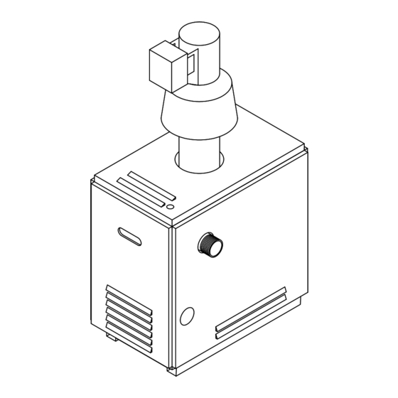
Models SG-135-E to SG-270-E
Advertisement
Table of Contents

Related Manuals for Super Hot SG-135-E


Summary of Contents for Super Hot SG-135-E
- Page 1 INSTALLATION AND SERVICE MANUAL INSTALLATION AND SERVICE MANUAL SG SERIES BOILERS SG SERIES BOILERS FOR MODELS SG-135-E TO SG-495-E FOR MODELS SG-135-E TO SG-495-E SEE REAR COVER FOR INDEX SEE REAR COVER FOR INDEX Models SG-135-E to SG-270-E Improper installation, adjustment, alteration, service or maintenance can cause property...
-
Page 2: Dimensions And Specifications
Minimum clearances to combustible material: Top 24” (610 mm), Sides 2" (51 mm), Rear 2" (51 mm), Flue 6" (153 mm) APPROVED FOR COMBUSTIBLE FLOORS & CLOSET INSTALLATION. The Super Hot product improvement program may result in changes to the design and / or specifications being made without notice. SHIPPING... - Page 3 Minimum clearances to combustible material: Top 24” (610 mm), Sides 2” (51 mm), Rear 2” (51 mm), Flue 6" (153 mm) APPROVED FOR COMBUSTIBLE FLOORS & CLOSET INSTALLATION, do not install on carpeting. The Super Hot product improvement program may result in changes to the design and / or specifications being made without notice. SHIPPING...
- Page 4 SG Series Boilers – Installation and Service Manual Boiler Water Flow Data NOTE: The boiler should be properly sized for its heating application and maintain an adequate water flow rate during operation. Significantly oversizing the boiler or decreasing boiler water flow rate will cause excessive stage cycling and may result in premature failure of components.
-
Page 5: About Our Manuals
SG Series Boilers – Installation and Service Manual ABOUT OUR MANUALS Your Super Hot boiler has been provided with two manuals: • User's Information Manual - This manual is intended for the owner or user of the boiler and provides information on routine operation and maintenance, and emergency shutdown. - Page 6 SG Series Boilers – Installation and Service Manual LIGHTING INSTRUCTIONS FOR INTERMITTENT ELECTRONIC IGNITION WITH COMBINATION GAS VALVE. 1. This boiler is equipped with an ignition device NOTE: On some gas valves the knob cannot which automatically lights the pilot. Do not try be turned to "OFF"...
-
Page 7: Run Mode
SG Series Boilers – Installation and Service Manual TO TURN OFF GAS TO THE BOILER OR EMERGENCY SHUT-OFF WARNING Should boiler overheat, or the gas supply fail to shut off, do not turn off or disconnect the electrical supply to the circulating pump. Instead, shut off the gas supply at a location external to the boiler. -
Page 8: Installer Mode
SG Series Boilers – Installation and Service Manual 1.6.2 INSTALLER MODE To enter the adjustment mode: 1. Press with Up ▲, Down ▼, and “I” keys (see Figure 1) simultaneously for three seconds. 2. Press and release the “I” key until the parameter (listed in the Table 2) requiring adjustment is displayed. -
Page 9: Controller Mounting
SG Series Boilers – Installation and Service Manual 1.6.3 OPERATING CHECKOUT After adjusting parameters, put the boiler into operation and observe operation through at least one complete cycle to make sure that the controller operates properly. See controller troubleshooting section to assist in determining boiler operation. - Page 10 SG Series Boilers – Installation and Service Manual Display State Specific Description Code Operation Sequence Idle/Standby The boiler is in standby - no call for heat StA ↔1 Run circulator Heat request present but boiler water temperature sufficiently high to run circulator pump only (no ignition sequence) Thermostat Calls For Heat Self Test...
- Page 11 SG Series Boilers – Installation and Service Manual If the controller is displaying “ ” followed by a number, use the error code definitions in the Table 4 to determine the problem and possible causes. Table 4 Error Codes Display State Solution The end switch contacts stuck closed.
-
Page 12: Bc-1 Controller (For 2 Stage Boilers Only)
SG Series Boilers – Installation and Service Manual BC-1 CONTROLLER (FOR 2 STAGE BOILERS ONLY) WARNING For boilers equipped with the BC-1 Controller, read all instructions in this manual and the BC-1 Controller Manual before placing the boiler in operation or making adjustments to the controller. - Page 13 SG Series Boilers – Installation and Service Manual Field wiring to terminal block TB4 Figure 3 – Field wiring to terminal block TB4...
-
Page 14: Electrical Connections
SG Series Boilers – Installation and Service Manual Electrical Connections For all electrical connections: Strip wire ends and insert into the terminal block. Tighten terminal screw clamps to securely hold the wire. CAUTION - Risk of damage to the controller - Do not apply power to any connections on terminal block TB4. - Page 15 SG Series Boilers – Installation and Service Manual 1.7.1 BC-1 CONTROLLER OPERATION When the controller is powered, the controller enters the operating mode if there are no sensor or high limit errors present. The user should select one of the following modes from the controller adjust menu: Mode 1 - Setpoint operation using parallel piping: Operates boiler stages to maintain fixed temperature at boiler outlet sensor when a heat demand is present.
- Page 16 SG Series Boilers – Installation and Service Manual MODE 4 ONLY (Outdoor reset and reset override) S1 = Boiler Outlet Sensor 071 S2 = Boiler Inlet Sensor 071 Pump1 = Boiler Pump Pump2 = DHW Pump A1 = DHW Aquastat Pump T1 = Thermostat Pump...
-
Page 17: Installation Codes And Requirements
SG Series Boilers – Installation and Service Manual Installation Instructions Section 2 RECEIVING INSPECT SHIPMENT FOR POSSIBLE DAMAGE. All goods are carefully manufactured, inspected, checked and packed by experienced workers. The manufacturer's responsibility ceases upon delivery of goods to the carrier in good condition. Any claims for damage, shortage in shipment or non-delivery must be filed immediately against the carrier by the consignee. -
Page 18: Gas Service Piping
SG Series Boilers – Installation and Service Manual GAS SERVICE PIPING The boiler and its gas connection must be leak tested before placing the boiler in operation. The gas controls furnished are suitable for a maximum operating gas pressure of 1/2 psi (14 inches water column). - Page 19 SG Series Boilers – Installation and Service Manual These chemicals are especially commons near swimming pools, beauty shops, dry cleaning establishments, laundry areas, workshops, and garages. The warranty is void when failure is due to corrosion. VENTING The responsibility of providing a suitable vent of adequate draft capacity and in good usable condition is that of the gas fitter/installer.
-
Page 20: Automatic Vent Damper
SG Series Boilers – Installation and Service Manual d) Place in operation the boiler being inspected. Follow the lighting instructions. Adjust the thermostat so the boiler will operate continuously. e) Test for spillage at the draft hood relief opening after 5 minutes of main burner operation. Use the flame of a match or candle, or smoke from a cigarette, cigar or pipe. -
Page 21: Corrosion Prevention (Internal)
Do not draw water from the heating system for cleaning, flushing, etc. Super Hot SG series boilers are designed for use in closed loop systems and are not intended for open systems, as in heating pool water or systems where water is constantly replenished. Operating the boiler in an open system will result in premature failure of the heat exchanger. -
Page 22: Pressure Relief Valve
SG Series Boilers – Installation and Service Manual water may overcool the flue gases, resulting in reduced vent suction. These are natural phenomena and are independent of the boiler design. As a guide to avoiding such corrosion and draft problems, it is imperative that the return water be not less than 135°F (57°C). -
Page 23: Pre-Start-Up
SG Series Boilers – Installation and Service Manual Startup Instructions Section 3 PRE-STARTUP a. Fill entire heating system with water and vent or purge air from system. Add water as needed to reach boiler operating pressure. Water should be of suitable quality. Do not use water with high hardness. -
Page 24: Check Burner System
SG Series Boilers – Installation and Service Manual 8) Check manifold pressure reading on the manometer and make necessary adjustments. Check that burner input matches rating plate input. 9) Return thermostat and controls to normal operation settings. b. Intermittent pilot with non-combination gas valve This boiler does not have a continuous pilot flame. -
Page 25: For Canada
SG Series Boilers – Installation and Service Manual AQUASTAT ADJUSTMENT An optional aquastat may be installed to control the main burner firing by sensing outlet water temperature. The optional aquastat should be set a minimum of 20°F (10°C) above the setting of the high limit of the integrated boiler controller. -
Page 26: Check For Draft Hood Spillage
SG Series Boilers – Installation and Service Manual Small adjustments to the input rate can be made by varying the manifold pressure. Normally it should be adjusted no more than 0.2 inch w.c. for natural gas or 0.5 inch w.c. for propane from the manifold pressure specified on the rating plate. -
Page 27: Check For Gas Leaks
SG Series Boilers – Installation and Service Manual CHECK FOR GAS LEAKS To identify gas leaks, smell for gas around boiler area and gas piping connections (See Section 1.1). To check a specific area for leakage, spray a mixture of soap and water onto the suspected area – active bubbling indicates a gas leak. -
Page 28: Service & Maintenance Instructions
SG Series Boilers – Installation and Service Manual Service & Maintenance Instructions Section 4 SERVICE & MAINTENANCE INSTRUCTIONS WARNING Label all wires prior to disconnection when servicing controls. Wiring errors can cause improper and dangerous operation. WARNING If any part of this boiler has been under water, inspect the boiler and replace any part of the control system and any gas control which has been under water. -
Page 29: Service Checklist
SG Series Boilers – Installation and Service Manual SERVICE CHECKLIST Reference Section Do not store anything against the boiler or allow dirt or debris to accumulate in the area immediately surrounding the boiler. The flow of supply and exhaust air must not be obstructed. -
Page 30: Refractory Handling Procedure
SG Series Boilers – Installation and Service Manual CAUTION: WATER REPLENISHMENT Avoid unnecessary replenishment of system water. It can allow oxygen to enter the system and cause serious corrosion problems. As well, an excessive amount of minerals may be deposited in the heat exchanger. - Page 31 SG Series Boilers – Installation and Service Manual Replacement Parts Section 5 NOTE: To supply the correct part it is important that you state the boiler model number, serial number and type of gas when applicable. Any part returned for replacement under standard company warranties must be properly tagged with Return Goods Authorization Form (R.G.A.), completely filled in with the boiler serial number, model number, etc., and shipped to the Company freight prepaid.
- Page 32 SG Series Boilers – Installation and Service Manual SG Series Boilers – Installation and Service Manual...
- Page 33 SG Series Boilers – Installation and Service Manual...
- Page 34 SG Series Boilers – Installation and Service Manual Wiring Diagrams Section 6 Simplified Wiring Instructions for models SG-135 to SG-270 IMPORTANT • Disconnect power source to boiler before wiring zone control board. • All wiring must comply with applicable codes, ordinances and regulations. •...
- Page 35 SG Series Boilers – Installation and Service Manual...
- Page 36 SG Series Boilers – Installation and Service Manual...
- Page 37 SG Series Boilers – Installation and Service Manual...
- Page 38 SG Series Boilers – Installation and Service Manual...
- Page 39 SG Series Boilers – Installation and Service Manual SG Series Boilers – Installation and Service Manual...
- Page 40 SG Series Boilers – Installation and Service Manual...
- Page 41 SG Series Boilers – Installation and Service Manual...
-
Page 42: Troubleshooting
SG Series Boilers – Installation and Service Manual TROUBLESHOOTING Section 7 Problem Possible Cause Solution • • Boiler will not fire. No power. Check power switches and wiring. • • No gas supply to boiler. Check gas source and pressure. •... - Page 43 SG Series Boilers – Installation and Service Manual Problem Possible Cause Solution • High voltage wiring is loose, broken or Pilot flame will not light on • No spark. grounded. Repair wiring. electronic ignition. • • Ignition electrodes are damaged. Replace electrodes.
- Page 44 SG Series Boilers – Installation and Service Manual INDEX Section 8 Section Page Dimensions and Specifications – For Models SG-135 to SG-270..............2 Dimensions and Specifications – For Models SG-315 to SG-495..............3 Boiler Water Flow Data ..........................4 About Our Manuals ............................5 Lighting Instructions.........................
Need help?
Do you have a question about the SG-135-E and is the answer not in the manual?
Questions and answers