
Summary of Contents for Superformance Coupe
- Page 1 Superformance Coupe Owner’s Manual Operational Guide Warranty First Edition November 19, 2004...
- Page 3 Authorized Dealer Model Superformance Coupe Chassis Number: SPC_______________________________ Color: ___________________________________ Stripes: ___________________________________ Purchased by: ___________________________________ Purchase Date: ___________________________________ Page i...
- Page 4 Superformance® is a registered trademark of Superformance International Inc. Compiled by Brett Jackson, Hi-Tech Automotive, Port Elizabeth, South Africa. Edited by Mike Stenhouse, Second Strike, the Superformance Owners Group, Davidson, North Carolina. Published by Superformance International Inc., Newport News, Virginia.
-
Page 5: Table Of Contents
TABLE OF CONTENTS List of Figures ..............vii Additional Information to Be Provided......ix Specifications..............1 General Specifications ..............1 Chassis ....................1 Body....................... 2 Front suspension ..................2 Rear suspension ..................2 Steering ....................2 Pedal box....................2 Brakes ....................2 Cooling.................... - Page 6 Fuel Pump Toggle Switch..............13 Windshield Wiper Rotary Switch ............14 De-Mist Toggle Switch................ 14 Windshield Washer Toggle Switch............14 Headlight Toggle Switch ..............14 Spot Light Toggle Switch ..............14 Number Toggle Switch ................ 15 Radiator Fan Override Toggle Switch ..........15 Engine Compartment / Exhaust Fan Toggle Switch ......
- Page 7 Maintenance ..............33 Battery....................33 Battery....................33 Main Power Cut Off Switch..............33 Wheels and Tires................34 Emergency Jacking Points - Front ............36 Emergency Jacking Points - Rear ............37 Tire Pressures..................39 Towing....................40 Alignment Specifications ...............42 Recommended Settings................ 42 Achieving the Settings - Front ............. 43 Understanding Your Graph ..............
- Page 8 Rear Number Plate Light ..............63 Fuse Box Tray Location and Components........65 Fuse Cluster # 1 ................... 65 Relays....................66 Fuses ....................66 Immobilizer..................67 Fuse Cluster # 2 ................... 67 Relays....................69 Fuses ....................69 Wiring Harness Diagrams ..............70 Dash Harness Map ................
-
Page 9: List Of Figures
LIST OF FIGURES Figure 1 Superformance Coupe..............1 Figure 2 Superformance Chassis, Front View..........3 Figure 3 Superformance Chassis, Rear View..........3 Figure 4 Speedometer and tachometer ............7 Figure 5 Gauges .................... 8 Figure 6 Fuel pressure gauge ..............10 Figure 7 Controls and switches .............. - Page 10 Figure 43 Drive pin holes in rim center ............38 Figure 44 Drive pins on hub center ............... 39 Figure 45 Towing eye and mounting bolt ............. 40 Figure 46 Front tow hook mount points ............41 Figure 47 Rear tow hooks mount points ............41 Figure 48 Front wheel toe vs.
- Page 11 ADDITIONAL INFORMATION TO BE PROVIDED The Coupe Owner’s Manual provides places to write information that is specific to your car. To be provided by owner and/or Superformance dealer Vehicle and owner information............i Keys....................27 To be provided by engine builder/installer Minimum, maximum, break-in engine speeds ........
- Page 12 Page x...
-
Page 13: Specifications
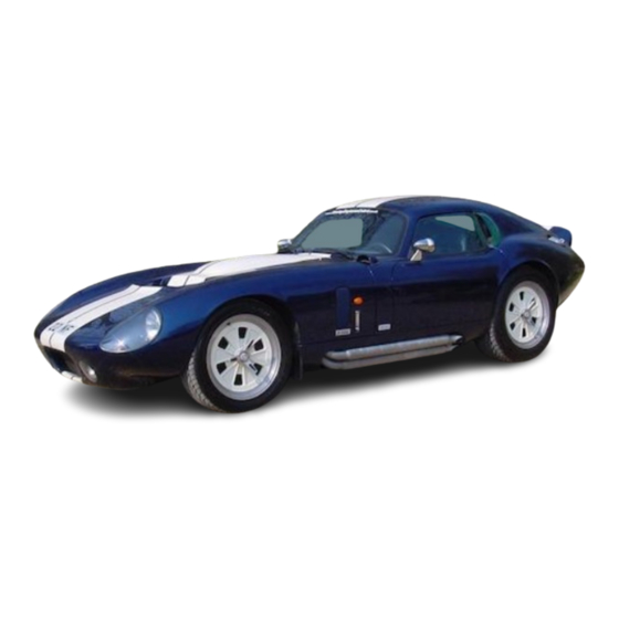
[Figure 1 - Superformance Coupe] The vehicle is supplied by Superformance as a complete and fully equipped rolling chassis less engine and transmission. Please check with the installer of your engine and transmission for break-in details and specifications for your engine and transmission and record the information in the space provided in this manual. -
Page 14: Body
Body Composite construction with superior aerodynamics. Hand laid fiberglass panels with Vinyl ester resin. All mounting points plated prior to lamination. Forward hinging doors and hood double skinned for added re-enforcement. Front suspension Fully independent suspension using unequal length A-arm design, adjustable coil springs over telescopic shock absorbers and anti roll bar. -
Page 15: Figure 2 Superformance Chassis, Front View
[Figure 2 – Superformance Chassis, Front View] [Figure 3 – Superformance Chassis, Rear View] Page 3... -
Page 16: Exhaust System
Mechanical Components Engine The Superformance Coupe has been designed to use: • A Ford 351 Windsor block or aftermarket equivalent with standard 9.5 inch deck height • Cylinder heads with exhaust ports in the stock location and... -
Page 17: Transmission
Transmission The Superformance Coupe is designed to use the Tremec T-56 6-speed manual gearbox from TTC (Transmission Technologies Corporation). The following speeds are the maximum calculated speeds based on recommended tire size, T-56 gear ratios, 3.46 final drive, and a 6000 rpm redline. -
Page 18: Wheels And Tires
Wheels and Tires Front Wheels ..... Aluminum 18" x 8” peg drive knock off Rear Wheels ....Aluminum 18” x 10” peg drive knock off Design Tire Sizes Front ..................255/45-18 Rear ...................285/50-18 Optional Tire Sizes Front ..................255/40-18 Rear ...................295/45-18 NOTE: Be sure to obtain a speed rating consistent with the speeds you expect to drive. -
Page 19: Operation
PERATION Instrumentation Full instrumentation, gauges and warning lights are provided with the Superformance rolling chassis. The gauges and warning lights must be correctly hooked up during the engine and transmission installation to function properly. The gauge and warning light readings are dependant on engine and transmission specifications and installation procedures. -
Page 20: Oil Temperature Gauge
IMMOBILIZER [Figure 5 - Gauges] Oil Temperature Gauge The oil temperature gauge (3) indicates the engine oil temperature in degrees Fahrenheit. The oil temperature during normal driving should be approximately the same as the water temperature. It will be somewhat lower until the engine fully warms up and during cold weather. -
Page 21: Oil Pressure Gauge
proceeding. Water temperatures above 210 degrees Fahrenheit during normal driving indicate a problem that needs to be corrected. For those more familiar with Centigrade: Fahrenheit Centigrade 100....38 140....60 150....66 190....88 230....110 270....132 280....138 290.... -
Page 22: Fuel Pressure Gauge
ALTERNATOR: When the engine is running the Volt meter will show the charging voltage from the alternator to the Battery. BATTERY: When the engine is off and ignition turned to position 1 the volt meter will show the condition of the battery power in volts. -
Page 23: Controls And Switches
Controls and Switches Steering wheel position [Figure 7 - Controls and switches] NOTE: For digital watch owners, clockwise is top to the right, counterclockwise is top to the left. Ignition Switch The ignition switch (9) has 3 positions: Accessory – key turned counterclockwise (to left) Only the radio and the DC accessory power ports have electrical feed with the ignition switch in this position. -
Page 24: Horn
When the headlights are turned on, click the switch on the back of the tip of the turn signal stalk to switch between high beams and low beams. When the high beams are on, the hi-beam pilot light (34) will be on. When the headlights are not on, clicking the switch on the turn signal stalk flashes the high beams. -
Page 25: Climate Control Air Flow Directional
Climate Control Air Flow Directional This control (14) has 4 settings. Air flow to head only. II Air flow is 70% head and 30% feet III Air flow 30% head and 70% feet IV Air flow to feet only From position II to position III, the airflow varies continuously from 70/30 to 30/70 head to feet. -
Page 26: Windshield Wiper Rotary Switch
the ignition is turned off, it is a good idea to turn off the electric fuel pump switch as well. Remember to turn it back on when you start the car. If the pump is switched off (up), the car may start, but will shut down in a short while when the fuel supply in the carburetor bowl is used up. -
Page 27: Number Toggle Switch
Number Toggle Switch (Optional) All coupes have plugs in the door loom for the connection of a light on the door to illuminate the racing number. Toggle the switch (24) downward to activate this light. Radiator Fan Override Toggle Switch The radiator fans are switched on automatically when the engine temperature exceeds 203 to 207 degrees Fahrenheit and when the air conditioning is on. -
Page 28: Adjustable Air Vents
The interior light switch has 3 positions: 1) Door activated – “ON” when door open 2) Manual light “OFF” position 3) Manual light “ON” position Adjustable Air Vents These dash mounted vents (27) are fully adjustable in all directions and are situated above the center gauges and air conditioner controls [Figure 10 - Adjustable air vents] Removable Cover for Radio Fitment... -
Page 29: Manual Door Operation
DC power accessory ports Door release buttons [Figure 11 - Door release [Figure 12 - Door release button driver’s side] button passenger’s side and DC power accessory ports] Manual Door Operation The doors can also be manually opened from inside the cockpit using the door levers housed in recesses in the bottom rear of the door panel. -
Page 30: Remote Immobilizer
Remote Immobilizer A remote immobilizer is supplied with the vehicle. The remote immobilizer is used to unlock the doors (two clicks) and to unlock the ignition (one click). See page 26 for doors and page 25 for starting. [Figure 14 - Remote immobilizer] DC Power Accessory Ports These can be used to supply power to 12 volt plug-in automotive accessories (See Figure 12 on page 17) -
Page 31: Gear Lever
Gear Lever The gear change layout for the 6 speed T-56 transmission is depicted on the top of the gear knob. Always select neutral before starting engine. The Tremec T-56 gearbox is equipped with a reverse gear lock out switch which ensures that reverse gear can only be selected whilst the car is stationary and the clutch AND brake pedals are depressed. -
Page 32: Ignition / Alternator Warning Light
Ignition / Alternator Warning Light It is normal for the Ignition / alternator warning light (32) to be on when the ignition is on and the engine is not running. If the Ignition / alternator warning light are on for more than a few seconds when the engine is running, it indicates a problem with the alternator. -
Page 33: Storage
The coupe has a fuel inertia switch fitted inside the cockpit. It is located at the front edge of the passenger’s side kick panel. (Next to right foot when seated – See Figures 18 and 19 above). The button is on top of the switch. -
Page 34: General Stowage Compartments
General Stowage Compartments There are 2 stowage compartments incorporated into the rear panel in the trunk. Each compartment has a stowage capacity of 3.5 liters. [Figure 22 - General stowage compartments] [Figure 23 - Inside the stowage compartment] Page 22... -
Page 35: Windshield Washer Bottle
Windshield Washer Bottle The windshield washer bottle is housed in the left hand side rear panel in the trunk. [Figure 24 – Washer bottle [Figure 25 – Washer bottle compartment] reservoir] Page 23... -
Page 36: Jack Compartment
Jack Compartment The scissor jack compartment is housed in the right hand side rear panel and contains the scissor jack and cranking handle, the lead knock off hammer which is used to remove the wheel spinners and an aerosol inflatable tire product for the inflation of a tire in the case of a puncture. -
Page 37: Start Procedure
Start Procedure Apply the handbrake and insert the key into the ignition. Depress the clutch pedal. Put the gear lever into neutral. The engine can only be started in neutral. Turn the key clockwise to position III to activate the electrical circuits. -
Page 38: Running In Procedure
500 miles of driving to bed in the friction materials. Vehicle Entry, Access and Refueling Doors Your Superformance Coupe is fitted with a remote entry system, with no external key locks or door handles for originality and enhanced security. The unlocking and opening procedure is... -
Page 39: Keys
CAUTION: Although the absence of key locks or door handles does enhance the security of your vehicle, it does however raise the possibility that you may not be able to gain access yourself. E.G keys and immobilizer remote control accidentally locked inside the car OR in the case of a flat battery. -
Page 40: Hood
Hood [Figure 29 - Hood latch] The hood (also known as the bonnet) is latched by two lever type hood latches at the rear of the hood on the sides. Access under the hood is gained via these two levers. When the hood is latched, the latch handles point towards the floor and lay in a recess in the hood itself. -
Page 41: Trunk
Open and close the hood with care to protect the car finish and the latch mechanisms. Care should be taken when opening the hood in windy conditions Trunk Access to the trunk is gained via a lock located in the rear of the car just below the spoiler (See Figure 30 below). -
Page 42: Refueling
Refueling A Le Mans vintage competition style gas filler and cap is fitted. To open the cap, press down on the latch. [Figure 31 - Le Mans vintage competition style gas filler] [Figure 32 - Locking type gas cap] The cap will spring open. A locking type gas cap is fitted inside the Le Mans cap for additional security. -
Page 43: Seats
Seats The hand made seats are upholstered in leather. The seats are adjustable fore and aft by 4”. Both seats have 35 ¾” of headroom. To adjust the driver’s seat, reach down in front of the seat and locate the lever. Lift and hold the lever, move the seat fore or aft to the desired position, then release the lever. -
Page 44: Seat Belts
To decrease the lumbar support, simply un-screw the valve on the hand pump (See Figure 33 above) which releases the air in the lumber support cushion. Close the valve again when satisfactory lumber has been achieved. Seat Belts The seat belts are mounted in 3 points with an inertia reel mechanism. -
Page 45: Maintenance
AINTENANCE Battery Battery The battery recommended by Superformance is a sealed for life battery and therefore should not need regular maintenance or renewal. The battery is located in the engine bay on the lower right hand side. To gain access to the battery, two metal panels must be removed by loosening and removing four M6 cap screws using a 4mm Allen key. -
Page 46: Wheels And Tires
Wheels and Tires The vehicle is fitted with Superformance aluminum peg drive wheels with polished rim and painted center. TIGHTEN LOOSEN FRONT Left side rear wheel [Figure 35 – Removing left side wheels] The left side front and rear wheel spinners are loosened by turning them counterclockwise and tightened by turning them clockwise. - Page 47 If a wheel has to be removed, front or rear, the knock-on nut should be struck with a soft hammer (lead or urethane) in the direction of the wheel rotation when moving forward. The lead hammer can be located in the stowage compartment on the right hand side rear panel in the trunk area.
-
Page 48: Emergency Jacking Points - Front
Emergency Jacking Points - Front To jack up the FRONT, remove the scissor jack and jack handle from the stowage compartment on the right hand side rear of the trunk area. (See Figure 26 on page 24). Open the hood for improved visibility and access. -
Page 49: Emergency Jacking Points - Rear
[Figure 39 - Scissor jack locating [Figure 40 - Hood raised, point for right hand front jack slid into position suspension] under right hand lower control arm] Emergency Jacking Points - Rear To jack up the REAR, use the scissor jack and jack handle as used for the front. -
Page 50: Figure 41 Scissor Jack Locating Point For Left Hand Rear Suspension
[Figure 41 - Scissor jack [Figure 42 - Scissor jack locating point for left hand locating point for right hand rear suspension] rear suspension] Carefully jack up the car. Ensure that the jack has a secure positioning on the lower control arm before removing the wheel. If available, support the car with axle stands under the lower control arm at the outer end of the suspension arm. -
Page 51: Tire Pressures
[Figure 44 – Drive pins on hub center] The spinner seating face should be coated with anti-seize compound before reinstalling. The spinner nut is tightened in reverse rotation direction. It is recommended that the spinner nut be tightened with a urethane hammer rather than a lead hammer to avoid over tightening. -
Page 52: Towing
Towing Three (3) towing eyes and bolts are provided with your vehicle for tow rope attachment. [Figure 45 - Towing eye and mounting bolt] These must be stored in the vehicle for use in emergency towing situations. It is suggested that you purchase a 22mm spanner and store it with the towing eyes and bolts. -
Page 53: Figure 46 Front Tow Hook Mount Points
There is one attachment bush in the chassis at the rear, just behind the differential (See Figure 47 below) FRONT OF CAR [Figure 46 - Front tow hook mount points] [Figure 47 - Rear tow hooks mount points] NOTE: The hoop of the towing eye must be angled in the direction that you are towing Page 41... -
Page 54: Alignment Specifications
The settings and instructions below are for the Superformance Coupe and are base settings which will give a good ride for street use. Read through this entire section to familiarize your self with the procedure before starting the job. -
Page 55: Achieving The Settings - Front
sizes should not affect wheel alignment. Speedometer calibration and ride height may change. Front Ride Height is measured from the ground to the bottom of the main chassis tube (3”OD) just below the front lower control arm (LCA) forward mount. In other words just forward from the tow eye mount bush that is welded to the chassis tube. -
Page 56: Understanding Your Graph
FRONT WHEEL TOE vs. WHEEL MOVEMENT -2.5 -1.5 -0.5 TOE IN TOE OUT recommended rack too low [Figure 48 – Front wheel toe vs. wheel movement] NOTE: – this graph is in mm, not inches. When measuring the bump steer plot it on a graph similar to the one above. -
Page 57: Achieving The Settings - Rear
Achieving the Settings - Rear Start by getting the control arms and trailing arm to the following lengths: Upper control arm Length should be set at 415mm (16.339”) from center of inner bushes to center of rod end. Lower control arm Length should be set at 588mm (23.150”) from center of outer bushes to center of rod end. -
Page 58: Figure 49 Setting Rear Static Toe
NOTE: The rear static toe is set by moving the LCA inner point backward to gain toe in and forward to gain toe out. Front of Car Toe out toe in [Figure 49 – Setting rear static toe] Once you have the camber and static toe set you need to measure the bump steer. -
Page 59: Figure 50 Rear Wheel Toe Vs. Wheel Travel
Upper half of the graph is bump and the lower half is droop. The left side is toe in and the right side is toe out. Or positive values on the axes are bump and toe out, while negative values are toe in and droop. -
Page 60: Understanding Your Graph - (Dynamic Toe)
Understanding Your Graph – (Dynamic Toe) Dynamic toe is the toe change that occurs under bump or droop. Too much toe in under bump: If you get more toe in under bump make the arm longer (e.g. 603mm). Too little toe in under bump: If you get less toe in under bump make the trailing arm shorter (e.g. -
Page 61: Figure 51 Rear Wheel Toe
REAR WHEEL TOE -2.5 -1.5 -0.5 -100 TOE - MM 601mm TRAILING ROD 602mm TRAILING ROD 602.5mm TRAILING ROD 603mm TRAILING ROD [Figure 51 – Rear wheel toe] Page 49... -
Page 62: Routine Check Up And Service
__________ miles Routine: __________ miles High speed: __________ miles NOTE: The Superformance oil pan has an 8 quart capacity. Transmission The transmission fluid specifications depend on the transmission installed. Your transmission provider should provide the oil change specifications. Fluid capacity: __________ quarts... -
Page 63: Differential
Differential The differential fluid specifications depend on the type installed. Your local Superformance dealer should provide the oil specifications. Oil capacity: __________ quarts Oil type: ______________________ NOTE: Rear axle fluid normally does not require replacement in absence of repairs. Brake Fluid The brake fluid reservoir is located at the left hand side rear of the engine bay, mounted on a bracket on top of the driver’s side foot... -
Page 64: Fuel Octane Requirement
If the brake fluid warning buzzer sounds, firstly check the brake fluid level. If this is low, top up with the recommended brake fluid (Any DOT 3 or DOT 4 fluid is recommended) If this is not the cause of the warning buzzer, please consult your Superformance dealer. NOTE:... -
Page 65: Power Steering Fluid
NOTE: Be careful when removing the header tank cap as the contents will be under pressure when hot. Power Steering Fluid The power steering fluid reservoir is situated at the front left of the engine, just behind the alternator. To remove the cap, simply twist the cap counterclockwise (to left) and lift. -
Page 66: Oil Usage Notes
Ford 351 Windsor based engine, Tremec T-56 6 speed transmission and Hydratrac limited slip differential (3.46:1). Various drive train combinations will fit into the Coupe. All will require differing fluid types and capacities. See pages 50 and 51 for fluids for your specific drive train. -
Page 67: Spark Plugs
Item Recommended Transmission oil ..Mobil 1 Synthetic ATF or equivalent Differential oil ... Motorcraft SAE 75W-140 Synthetic Real Axle Lubricant (or equivalent) Cooling system..Add 2 gallons universal antifreeze. Top up with water. Brake and clutch..Castrol SRF Racing Brake Fluid (or DOT 3 minimum) Power steering ... -
Page 68: Recommended Weekly Checks
If there seems to be damage, the vehicle should be taken to your local Superformance dealer for a comprehensive inspection. Page 56... -
Page 69: Exterior Cleaning
Exterior Cleaning By Hand The recommended method of cleaning your coupe is to wash it by hand using a specialist car shampoo or mild detergent. A low pressure hose should then be used to rinse the vehicle before drying with Chamois leather. It is not advisable to use specialist cleaners on the vehicle wheels, or to use other specialist “road... -
Page 70: Electrical
(1) Sylvania bulb part number. Sylvania uses a suffix such as CB (Cool Blue), XV (Xtra Vision), and LL (Long Life) for variations. (2) See your Superformance dealer for this bulb (3) Bulb and wire come as a replacement unit. OSRAM is the parent of Sylvania. -
Page 71: Figure 55 Remove Fastening Screw
NOTE: The clear plastic headlight / indicator cover and sealing rubber were fitted using a little silicon sealer between the rubber and the body. Sealer MUST be applied in this area when replacing them after the bulb change [Figure 55 - Remove [Figure 56 - Remove plastic fastening screw] cover]... -
Page 72: Figure 59 Plastic Access Cover
[Figure 59 - Plastic access [Figure 60 - Loosen screw cover] through hole] Remove the surround to remove the light, remove the fastening screw and tip the light forward, to gain access to the rear of the housing. Pull the plug out. Remove the bulb by compressing the two ends of the spring wire clip together. -
Page 73: Figure 63 Unplug The Light
[Figure 63 - Unplug the [Figure 64 - Compress spring light] clip and remove bulb] Spot Lights – Front Using a Phillips screw driver, lift the sealing rubber and remove the four screws securing the clear plastic spot light cover. Remove the four screws securing the plastic shroud. -
Page 74: Figure 67 Remove Fastening Ring
Lean the spot light forward. Loosen and remove the screw and nut holding the fastening ring. Remove the fastening ring. Unplug the white wire at the terminals. [Figure 67 - Remove fastening [Figure 68 - Unplug white ring] wire] Separate the lens from the housing by pulling it forward. Loosen and remove bulb using a short flat screw driver. -
Page 75: Rear Lights
Rear Lights The BRAKE / PARK lights, REAR INDICATORS and REVERSE LIGHT share the same type of light housing. Therefore the procedure for bulb replacement is the same. Using a thin flat screw driver, carefully remove the chrome plated rim from the rubber seal by gently levering it out. Then, using the same method, remove the lens. -
Page 76: Figure 73 Removal Of Number Plate Lamp Cover
[Figure 73 - Removal of number plate lamp cover] Refit the cover by reversing the removal procedure. Page 64... -
Page 77: Fuse Box Tray Location And Components
Fuse Box Tray Location and Components Fuses and relays can be found in two locations. See Fuse Cluster #1 on page 66 and Fuse Cluster #2 on page 69. Fuse Cluster # 1 These fuses and relays are mounted on a hinged tray under the dash on the driver’s side. -
Page 78: Relays
[Figure 75 - Cluster 1 Relays and fuses under the dash] Relays Lights on warning “GONG” Low coolant warning light Left side door opener Climate control re circulation Climate control re circulation Climate control re circulation Fuses Left side park –Registration plate ....7.5 A Right side park –... -
Page 79: Immobilizer
14 Wiper – wash..........15 A 15 HVAC............15 A 16 HVAC............15 A 17 Stop – Reverse solenoid ......10 A 18 Dome – Immobilizer ........10 A 19 Hazard ............20 A 20 Cigar lighter – Door solenoid...... 20 A 21 Horn............. -
Page 80: Figure 78 Radiator Cowl And Fans
The cowl is held down at the front by a rubber o-ring on a hook. Insert finger into o-ring and unhook it by pulling it back. The cowl and attached fans can now be lifted up and back to remove. PULL O-RING TO UN-HOOK [Figure 78 - Radiator cowl... -
Page 81: Relays
[Figure 81 - Cluster 2 Relays and fuses in the engine bay] Relays Spot lights Air conditioner unit Exhaust fans Starter motor Radiator fans – 1 speed Neg. Radiator fans – 1 speed Pos. Radiator fans – A/C / Temp. signal Radiator fans –... -
Page 82: Wiring Harness Diagrams
Wiring Harness Diagrams The wiring harness has been divided into two sections. 1) The DASH HARNESS, Earth route and connectors. 2) The FRONT HARNESS and 8 pin connectors. Both sections have been broken down into loom extensions / branch clusters with item description, wire color, wire thickness and connecting wires. -
Page 84: Cluster Dh1
Cluster DH1 1.1 DOOR SWITCH 1.2 DOOR HARNESS CONNECTOR 1.3 BLOWER FAN/RECIRC/A-C THERMOSTAT DH1.1.1 BROWN/GREEN .75 TO DH13.1A -- TO DH13.2 PIN 7 -- TO DH13.3 PIN 2 -- TO DH15.1 RELAY 1 PIN 31b DH1.1.2 BROWN .75 SPLICED TO DH1.3 PIN 8 2.0 BW DH1.2 8 PIN MALE DH1.2.1. -
Page 85: Clusters Dh2 +Dh3
Clusters DH2 +DH3 DH2.1 WIPER MOTOR CONNECTOR DH2.2 RADIO DH2.1.1 GREEN/PURPLE TO 20.4 PIN 30 DH2.1.1 GREEN/PURPLE 1.5 TO 23.7 PIN 1 DH2.1.2 GREEN/BLACK 1.5 TO 20.4 PIN 53 JUMP TO PIN 31b DH2.1.3 GREEN/YELLOW 1.5 TO 20.4 PIN 53b DH2.1.4 GREEN 1.5 TO 20.4 PIN 31 DH2.1.5 BROWN 1.5 TO 8 DH2.2.1 RED/BLACK FLEX TO DH1.2 PINS 3 and 4... -
Page 86: Clusters Dh4, Dh5, Dh6, Dh7 + Dh8
Clusters DH4, DH5, DH6, DH7 + DH8 DH4 HORN BUTTON DH4.1 RED/YELLOW 1.5 TO DH15.1 FUSE 16 DH4.2 RED/YELLOW 1.5 TO DH 23.2 PIN 1 DH5 LOW BRAKE FLUID BUZZER DH5.1 BLACK .75 SPLICED TO BLACK 1.0 TO DH15.1 FUSE 5 DH5.2 BROWN/YELLOW .75 TO DH23.1. -
Page 87: Clusters Dh9, Dh10, Dh11 + Dh12
Clusters DH9, DH10, DH11 + DH12 DH9 WARNING LIGHTS DH9.1.1 GREEN/BROWN .75 TO DH6.P DH9.1.2 BROWN .75 TO DH8 DH9.2.1 BLACK .75 SPLICED TO DH 7.2 DH9.2.2 BLUE .75 TO 23.2 PIN 4 DH9.3.1 BLACK .75 SPLICED TO DH 7.2 DH9.2.2 YELLOW .5 TO 15.1 RELAY 2 PIN 30 DH10 DH10 SPEEDOMETER... -
Page 88: Clusters Dh13, Dh14 + Dh15
Clusters DH13, DH14 + DH15 DH13 DH13.1 DOOR SWITCH DH13.2 DOOR HARNESS CONNECTOR DH13.3 HIGH BEAM WARNING LIGHT DH13.1.1 BROWN/GREEN .75 SEE DH1.1.1 DH13.1.2 BROWN .75 TO 8 DH13.2 8 PIN MALE DH13.2.1. BROWN FLEX SPLICED TO 14 DH13.2.2. BROWN/WHITE FLEX TO DH15.2 RELAY 3 PIN 30 DH13.2.3. -
Page 89: Clusters Dh16, Dh17, Dh18 + Dh19
Clusters DH16, DH17, DH18 + DH19 DH16 DH16 METER LIGHTING DIMMER DH16 3 PIN DH16.1 GREY/BLACK .75 TO DH19.1 MALE DH16.2 GREY/RED TO DH15.1 FUSE 2 DH16.3 GREY/BLACK 1.5 TO .75 GREYS AT DH3 DH17 DH17 TURN/DIP SWITCH DH17.1 BROWN .75 TO DH8 DH17.2 BLUE/WHITE 1.0 TO DH23.2. -
Page 90: Clusters Dh20.1 To Dh20.6 (Switch Panel)
Clusters DH20.1 to DH20.6 (switch panel) DH20 DH20 SWITCH PANEL 12 13 Cluster s DH20.1 to 20.6 DH20.1 R/S DOOR OPENER SWITCH DH20.1.1 RED/GREEN 1.5 JUMP TO DH20.8.1 DH20.1.2 BROWN/WHITE FLEX TO DH1.2 PIN 2 WINDSCREEN WASHER SWITCH DH20.2 DH20.2.1 GREEN/BROWN .75 TO DH8.2 DH20.2.2 BROWN .75 TO DH20.9.2 DH20.2.3 BROWN .75 JUMP TO DH20.2.1 DEMIST SWITCH... -
Page 91: Clusters Dh20.7 To Dh20.13 (Switch Panel)
Clusters DH20.7 to DH20.13 (switch panel) DH20 DH20 SWITCH PANEL 12 13 Cluster s DH20.7 to DH20.13 DH20.7 L/S DOOR OPENER SWITCH DH20.7.1 BROWN/WHITE .75 TO DH15.1 RELAY 3 PIN 85 DH20.7.2 BROWN .75 TO DH20.14.2 R/S CIGAR LIGHTER DH20.8 DH20.8.1 RED/GREEN 1.5 TO DH20.1.1 DH20.8.1 RED/GREEN 1.5 TO DH20.14.1 DH20.8.2 BROWN 1.5 TO DH8... -
Page 92: Clusters Dh20.14 To Dh20.16 (Switch Panel) + Dh21
Clusters DH20.14 to DH20.16 (switch panel) + DH21 DH20 DH20 SWITCH PANEL 12 13 Cluster s DH20.14 to DH20.16 L/S GIGAR LIGHTER DH20.14 DH20.14.1 RED/GREEN 1.5 TO DH20.8.1 DH20.14.1 RED/GREEN 1.5 TO DH15.1 FUSE 14 DH20.14.2 BROWN 1.5 SPLICE TO BROWN 1.5 TO DH20.8.2 REVERSE LIGHT/SOLENOID DH20.15 DH20.15.1 BLACK/WHITE 1.0 TO DH15.1 FUSE 5... -
Page 93: Dh 20 Earth Route + Msd Ignition Connections
DH 20 Earth route + MSD ignition connections DH20 DH20 EARTH ROUTE BROWN 1.5 TO DH8 ALL OTHER 20.4 BROWN .75 20.16 20.2 20.3 20.7 20.9 20.10 SPLICE 20.8 BROWN 1.5 20.14 DH22 DH22 IGNITION MODULE CONNECTORS MSD IGNITION MODULE 4.0mm Main Feed 2.0mm Main Earth R/GN 1.0mm Ignition From Immobilizer... -
Page 94: Clusters Dh22 + Dh23
Clusters DH22 + DH23 DH22 DH22 IGNITION MODULE CONNECTORS FORD TYPE IGNITION MODULE. DH22.1 NOTE: FOR MSD IGNITION MODULE WIRES SEE PREVIOUS PAGE ( 84) 22.1 4 PIN MALE DH22.2 DH22.1.1 CLEAR TO DH23.4 PIN A DH22.1.2 BLACK TO DH23.4 PIN B DH22.1.3 BROWN 1.5 TO DH8 DH22.1.4 BLACK/GREEN 1.5 TO DH23.2 PIN 7 22.2 2 PIN MALE... -
Page 95: Clusters Dh23 + Dh24
Clusters DH23 + DH24 DH23 DH23 FRONT HARNESS CONNECTORS DH23.4 DH22.6 DH23.5 23.4 DEUTSCH 3 DH22.7 PIN FEMALE DH23.4.A CLEAR TO DH22.1.1 DH23.4.B BLACK TO DH22.1.2 DH23.4.C SCREEN (EARTH) SPLICE TO DH22.1.3 DH23.5. RED 4.0 TO 15.1 FUSES 11 - 16 23.5 6mm DH23.6.1 GREEN/BLACK .75 SPLICE TO DH23.3.1 EYELET... -
Page 96: Harness Connectors
Harness connectors HITECH COUPE DASH HARNESS CONNECTORS ALL CONNECTORS VIEWED FROM WIRE SIDE 22.1 4 PIN MALE 22.2 2 PIN MALE 1 CLEAR 1 NOT USED 2 BLACK 2 RED/GREEN .75 3 BROWN 1.5 4 BLACK/GREEN 1.5 15.2.1 10 PIN MALE... -
Page 97: Harness Connector's Cont
Harness connector’s cont. HITECH COUPE DASH HARNESS CONNECTORS ALL CONNECTORS VIEWED FROM WIRE SIDE 23.4 3 PIN FEMALE 23.5 6mm EYELET A. CLEAR RED 6.0 B. BLACK C. EARTH 23.6 6 PIN FEMALE 4. GREY/BLACK .75 1. GREEN/BLACK .75 5. GREY/RED .75 2. -
Page 99: Harness Wire Color, Thickness And Function
Harness Wire Color, Thickness and Function HITECH COUPE FRONT/REAR HARNESS CONNECTORS Colour Function MAIN SUPPLY R/GN COIL + BK/GN (ORANGE)* COIL - START RELAY CHOKE / ALT / RELAY IGN+ R/BU BRAKE LIGHT / REV L/O** + R/BU BRAKE LIGHT / REV L/O** RETURN... -
Page 100: Express Conditional Warranties, Inspection And Repairs
ARRANTIES NSPECTION AND EPAIRS IN GENERAL, it is the intention of Superformance Inc. and the Dealer, to provide our customers with a Superformance rolling chassis of unsurpassed quality, attention to detail, and safety. If the component vehicle succumbs to a mechanical defect covered by this warranty during the warranty period, we will remedy the problem at our expense. - Page 101 The vehicle’s paint shall be covered by a one (1) year conditional warranty against cracking, peeling, and/or any other defect resulting from seller’s workmanship, however, such warranties shall not apply to normal wear and tear or misuse. Such misuse would include, but is not limited to, leaving the vehicle exposed in extreme climates for extended periods of time.
- Page 102 (30) days to cure the problem. If in the event that new parts from a third party supplier or Superformance, Inc., are required and that delivery and installation of these new parts will...
- Page 103 This warranty gives the buyer specific legal rights which may vary from state to state. Neither Superformance Inc. nor the Dealer assumes nor authorizes any other person or party to assume for them any other liability in connection with this vehicle. No...
-
Page 104: Miscellaneous Terms And Conditions
Non-Affiliation: Neither Superformance Inc. nor the Dealer are affiliated either directly or indirectly with Ford Motor Company or Carroll Shelby. -
Page 105: Glossary
United States Postal Service in a certified format. Competition: Shall refer to any organized or unorganized contest of speed utilizing a Superformance Inc. product as mode of transportation. Customer: Shall be defined in the same relative terms as those defined in Glossary Item (R), “Purchaser”. - Page 106 Labor: Shall refer to physical work required by Superformance Inc. and/or Dealer employees for the purpose of repairing or maintaining the vehicle in question. Misuse: Shall refer to any application of Superformance products falling outside the reasonably anticipated use of the vehicle or its options.
- Page 107 Seller: Shall refer to both the Dealer and Superformance Inc. Side Exhausts and/or Side Pipes: Refers to the tubular...
-
Page 108: Notes
OTES _____________________________________________________ _____________________________________________________ _____________________________________________________ _____________________________________________________ _____________________________________________________ _____________________________________________________ _____________________________________________________ _____________________________________________________ _____________________________________________________ _____________________________________________________ _____________________________________________________ _____________________________________________________ _____________________________________________________ _____________________________________________________ _____________________________________________________ _____________________________________________________ _____________________________________________________ Page 96... - Page 109 _____________________________________________________ _____________________________________________________ _____________________________________________________ _____________________________________________________ _____________________________________________________ _____________________________________________________ _____________________________________________________ _____________________________________________________ _____________________________________________________ _____________________________________________________ _____________________________________________________ _____________________________________________________ _____________________________________________________ _____________________________________________________ _____________________________________________________ _____________________________________________________ _____________________________________________________ _____________________________________________________ _____________________________________________________ Page 97...
- Page 110 _____________________________________________________ _____________________________________________________ _____________________________________________________ _____________________________________________________ _____________________________________________________ _____________________________________________________ _____________________________________________________ _____________________________________________________ _____________________________________________________ _____________________________________________________ _____________________________________________________ _____________________________________________________ _____________________________________________________ _____________________________________________________ _____________________________________________________ _____________________________________________________ _____________________________________________________ _____________________________________________________ _____________________________________________________ Page 98...
Need help?
Do you have a question about the Coupe and is the answer not in the manual?
Questions and answers