Table of Contents
Advertisement
Advertisement
Table of Contents

Related Manuals for PIAGGIO VESPA RALLY 200


Summary of Contents for PIAGGIO VESPA RALLY 200
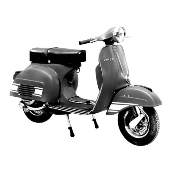
- Page 2 Fig. 1 – Vespa Rally 200...
-
Page 3: Table Of Contents
CONTENTS Performance and specifications Page Layout of controls Operating instructions Oil to be used of the fuel mixture Running in Tire pressure Operating and maintenance: Common operations to cart Maintenance Summary of Instructions for Maintenance Fault finding General specification 29-32 Accessories Electrical equipment 32-34... -
Page 4: Performance And Specifications Page
PERFORMANCE AND SPECIFICATIONS Consumption (according to CUNA Standards) : 3 It 100 Km. (78 mls U.S. gals; 94 mls/imp. gals), gasoline-oil mixture i. e. 2% oil. Max. speed (CUNA Standards): 110 Km/h (68 mph). Carrying capacity: 2 persons and 10 Kg. (22 lbs.) of luggage. - Page 5 It follows: 1) Engine regular running also with spark-plugs very dirty. 2) Starting facility when cold. 3) Light ignition and combustion of the fuel. 4) Higher life of the spark - plugs because of a smaller electrodes wear. 5) Unalterability, during the time, of the ignition advance because the traditional mechanical devices exposed to the wear (as the contact breaker cam, contact breaker, sliding block etc.) are not longer present.
-
Page 6: Operating Instructions
OPERATING INSTRUCTIONS Operation Instructions SECURITY LOCK 1. - Steering lock. a) Locking the handlebars To lock the vehicle, turn the handlebars anticlockwise up to the limit stop; rotate the key anticlockwise and push inwards. So that it thrusts the sliding bar against the steering column (see fig. - Page 7 OPERATING INSTRUCTIONS Fig. 3 - Steering lock on the steering column Fig. 4 - Front tool box lock 1. Normal position and locking operation – 2. locked position and unlocking operation. N. B. - The arrow indicates the operation to be carries out for unlocking (1) and for locking (2) the tool box.
-
Page 8: Running In
OPERATING INSTRUCTIONS Operation Instructions FUEL SUPPLY Use a mixture of gasoline (petrol) and pure mineral Oil SAE 30 at 2°/°: (Esso 2 - T Motor Oil; Shell Golden Motor Oil, Shell X - 100 2 T; Total 2 T). The mixture should be at 2% of oil by volume ( /4 pint of oil to 1 /2 gals of gasoline... - Page 9 OPERATING INSTRUCTIONS Operation Instructions Carry out the operations indicated on fig. 6. Do not STARTING use the choke when the engine is warm; as soon as the engine is running smoothly bring the starter control back to its normal position. With the engine running at idling speed declutch SETTING THE SCOOTER IN MOTION and rotate the gear change twist grip to the position...
-
Page 10: Operating And Maintenance
OPERATING AND MAINTENANCE: Common operations to carry out REMOVAL OF ENGINE COWLING - Pull the lever (1) - and turn to release from cowling. Swing the cowling outwards so that the front locating pin (2) is free of its housing. - Lift the cowling upwards from the front pivoting on its rear section: so that the clasp (3) releases from the chassis bracket. - Page 11 Fig. 8 – Gear Transmission 1. Gear change twist grip - 2. Clutch control lever - 3. Gear change cable - 4. Gear shifter - 5. Selector stem - 6. Selector spider - 7. 1st gear - 8. 2nd gear - 9. 3rd gear - 10. Top gear - 11.
- Page 12 OPERATING AND MAINTENANCE: Common operations to carry out ADJUSTMENT ON CARBURETTOR For adjusting the idling turn the slow running adjuster screw (on the air cleaner cover) (Fig. 9, n. 5). - On the carburettor body a set screw is provided for adjusting the throttle cable play; this screw is to be reset only if necessary or on dismantling and reassembly operations.
- Page 13 Fig. 9 - Fuel supply and distribution diagram 1. Combined fuel tap and sediment bowl. - A) Reserve; B) Open; C) closed - 2. Float - 3. Carburettor and air cleaner - 3/1. Air filter - 4. Calibrator for starter - 5. Throttle slide set screw - 6.
- Page 14 OPERATING AND MAINTENANCE: Common operations to carry out Operation Instructions For dismantling the wheels from the vehicle remove CHANGING WHEELS AND TIRES the nuts as indicated in fig. 10. On reassembly tighten said screws alternately and progressively. When a tire has to be removed, first deflate and DISMANTLING THE SPARE WHEEL then remove the nuts joining the two wheel rim (fig.
- Page 15 OPERATING AND MAINTENANCE: Common operations to carry out Operation Instructions Rotate the adjusting screw indicated in fig. 13 so BRAKE ADJUSTMENT that the wheel is completely free to rotate when the lever and brake pedal are in the resting position. The braking action should commence immediately the respective controls are operated.
- Page 16 Fig. 10 – Removing wheel from vehicle...
- Page 17 OPERATING AND MAINTENANCE: Common operations to carry out Fig. 12 – Dismantling the spare wheel Operation Instructions Remove engine cowl (Fig. 7), disconnect the H. T. SPARK PLUG REMOVAL lead and extract the spark plug using the box wrench as indicated in Fig. 15. Drain off through hole (Fig.
- Page 18 Fig. 13 – Front and rear brake adjustment Fig. 13 (2) – Front and rear brake adjustment...
- Page 19 Fig. 14 Dismantling the air cleaner Note - If the air cleaner case is taken off, it is also possible to gain access to the carburettor.
- Page 20 OPERATING AND MAINTENANCE: Common operations to carry out Operation Instructions DISMANTLING CYLINDER HEAD Strip off engine cowling, (Fig. 7), disconnect the H. T. lead, dismantle the <Cooling hood> , (fastenings ,<A>-<B>-<C>, fig. 17) and unscrew the four securing nuts by means of a box wrench. SUBSTITUTING BULBS Should one of the bulbs fail, before fitting a replacement, check that the socket contact points...
- Page 21 17 A) 17 B) Fig. 17 – Dismantling cooling hood from engine (A) and head (B)
- Page 22 OPERATING AND MAINTENANCE: Common operations to carry out Operation Instructions Since in this type of ignition there are not - as we TIMING CHECKING AND SETTING have said at page 6 - mechanical parts exposed to the wear, .the timing remains during the time practically unalterable.
- Page 23 OPERATING AND MAINTENANCE: Common operations to carry out Operation Instructions The correct setting of the main beam can be SETTING THE HEADLAMP obtained both horizontally and vertically as follows: Check that both front and rear tires are inflated to correct pressure: i. e. 1.2 and 2.5 Kg/cm2 (15.5 and 35.5 p.s.i.).
-
Page 24: Maintenance
MAINTENANCE Though the electronic ignition provides a regular running of the engine also when the spark plug is dirty or the electrodes setting is not correct, when difficulties of ignition occur, check the spark plug: clean in neat gasoline (petrol) and wire brush (or emery cloth) the electrodes;... -
Page 25: Summary Of Instructions For Maintenance
SUMMARY OF INSTRUCTIONS FOR MAINTENANCE AND LUBRICATION PRINCIPAL OPERATIONS TO CARRY OUT Gear box (top up) EVERY 4000 Km. (2400 mls) Fulcrum points of brake lever and pedal - Gear selector - Front suspension - Speedometer drive and transmission. Cleaning air filter in gasoline (petrol). Decoking cylinder head and piston. - Page 26 Esso Motor Oil 30; Esso 2 T Motor Oil ; Shell Golden Motor Oil ; Shell X - 100 2 T ; Total 2 T. , For operation : 1 . I Esso Beacon 3 ; Shell Retinax A ; Mobilgrea. se MP; Total Multis.
- Page 27 CLEANING THE VEHICLE Engine For cleaning the exposed surface of the engine use paraffin, a brush and clean rags. Bodywork. Washing. Painted parts should be washed down using a low pressure hose. Do not use a high pressure system as grit may be forced into the paint. When the dirt and grime becomes soft, sponge off using one of the <car type>...
-
Page 28: Fault Finding
FAULT FINDING When the machine does not run properly, inspect and rectify as explained below. If the suggested remedies are not sufficient in eliminating the trouble, consult your Dealer. Fault finding Remedies 1. - Fuel system - Carburation – Ignition. Lack of fuel. -
Page 29: General Specification
GENERAL SPECIFICATIONS Engine (see characteristics at pag. 5 and fig. 5) : the engine is pivoted to the chassis of the vehicle (fig. 21). The rear wheel if fitted on the outer side of the drive shaft. Lubrication of engine components (piston, cylinder, crankshaft main bearings) is effected by the oil in the fuel mixture. -
Page 30: Accessories
Fig. 21 - Installation of engine and suspension 1. Steering column and front suspension - 2. Engine - 3. Crankcase, clutch side, with swinging arm pivoted to frame - 4. Rear suspension spring and hydraulic damper assy. FRAME INTEGRAL CHASSIS (see fig. 1) : of pressed sheet steel with streamlined monocoque type structure. -
Page 31: Electrical Equipment
A six pole magneto - nominal voltage 6 V - supplies alternating current to the electrical equipment. The controls (switching levers, horn button) are located on the handlebars, R. H. into the main light and dip switch (Fig. 22). The engine cut-out button is located on the frame, under the hook for bag (see Fig. - Page 32 LOACATION OF ELECTRICAL EQUIPMENT Notice: The connector <A>, for connection of the flywheel cable with the electronic control box, is provided with colored reference points which correspond to the cables. Fig. 23 - Installation of electrical equipment Notice = For avoiding damages to the electronic control box, not disconnect the cables of the low tension socket, when the engine is running.
- Page 33 WIRING DIAGRAM Fig. 24 - Wiring diagram NOTICE: The loads on the bulbs and horn are connected in series with respect to the flywheel magneto coils, whereas the switch units are in parallel to the bulbs: the insertion of the lights and horn comes about by opening (instead of closing) the relative control switches.
-
Page 34: Identification Data
IDENTIFICATION DAT A Fig. 25 - Serial number stamped on frame (VSE 1 TXXXXXX) and on engine (VSE I MXXXXXX). Notice - These numbers should be quoted when ordering spare parts. - Page 35 PLEASE NOTE: SOME INFORMATION MAY VARY AS IT HAS COME FROM GENUINE / EDITED LAMBRETTA & VESPA BOOKS / ARCHIVE / ETC.
Need help?
Do you have a question about the VESPA RALLY 200 and is the answer not in the manual?
Questions and answers