Table of Contents
Advertisement
Advertisement
Table of Contents

Related Manuals for Otto Bock ParaGolfer

Summary of Contents for Otto Bock ParaGolfer
- Page 1 ParaGolfer Service Instructions...
-
Page 3: Table Of Contents
Service Instructions for the ParaGolfer Sports Wheelchair Table of Contents Page 1 General Information ......................5 1.1 Preface ........................5 1.2 Intended Use ......................5 2 Safety ..........................5 2.1 Explanation of Symbols ..................5 2.2 Standards and Directives ..................5 2.3 General Safety Instructions ...................6 2.4 S afety Requirements for the Use of Tools and Aids ..........7 2.5 ... - Page 4 4 | Ottobock ParaGolfer...
-
Page 5: General Information
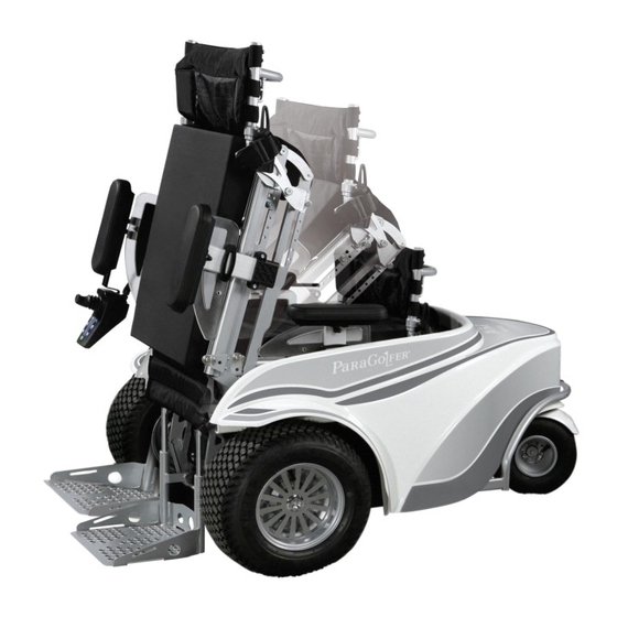
ParaGolfer is fully utilised. 1.2 Intended Use The ParaGolfer is designed solely for persons who are unable to work or have a walking impedi- ment for doing indoor or outdoor sports that require an upright body position. The ParaGolfer was specially designed for users who are able to independently move in a power wheelchair. -
Page 6: General Safety Instructions
NOTICE Risk of damage due to excessive heat or cold. The ParaGolfer may only be operated in the tempera- ture range from -25 °C to +40 °C (-13 °F to 104 °F). It must not be operated at temperatures outside this range. -
Page 7: S Afety Requirements For The Use Of Tools And Aids
Equipment used to raise loads must prevent the load from accidentally shifting in a dangerous manner, dropping in free fall or being accidentally released. When using lifting platforms, ensure that the ParaGolfer is centred on the platform and no parts project into the danger area. - Page 8 NOTICE Risk of damage due to improper preparation of maintenance tasks. • The ParaGolfer must be turned off and the fuse must be removed for all maintenance tasks. This does not apply to functional tests of the electrical components. • Secure the product to prevent it from tipping over or falling, e.g. off the workbench.
-
Page 9: S Afety Requirements For Maintenance Tasks On Electrical Components
Therefore, turn off the control unit whenever you do not need it. INfORMATION During extended periods of disuse or shipment of the ParaGolfer, remove the fuse from the battery case in order to prevent deep discharge of the batteries due to standby consumption. -
Page 10: Safety Requirements For Disposal
NOTICE Risk of damage due to falling. The empty weight of the ParaGolfer is 180 kg (397 lbs). For transpor- tation, only the designated carry handles may be used. Hoisting devices and transportation vehicles must have sufficient capacity. -
Page 11: Storage
If the power wheelchair is not moved for several days, permanent colour changes may occur where the wheelchair comes into contact with the surface it is standing on. Ottobock therefore recommends parking the wheelchair on a suitable surface during extended periods of disuse. ParaGolfer Ottobock | 11... -
Page 12: Required Tools And Aids
The storage location must be dry and have sufficient air circulation. There must not be any build- up of humidity. The ParaGolfer must not be subjected to any damaging exterior influences, e.g. rain, snow, or strong solar radiation during storage. -
Page 13: Information Display
Messages are shown on the control panel display: Display symbol(s) Information Driving menu with speed level and battery capacity Low battery capacity Charging process with drive lock Stand-up device Drive-away lock Creep speed Table 1 Information displays ParaGolfer Ottobock | 13... -
Page 14: Service And Maintenance
If you pull off the battery disconnect switch, the entire control of the ParaGolfer is blocked. To do so, turn the battery disconnect switch by 90° and then pull it off. -
Page 15: Cover Removal
❒ Allen wrench, size 6 Steps: 1. Move the seat with stand-up function up. 2. Loosen the six Allen head screws along the inner edge of the cover. 3. Remove the cover. fig. 6 Disassembling the cover ParaGolfer Ottobock | 15... -
Page 16: Cover Plates
6.5.2 Removing the Lower Cover Plate The lower cover plate is located at the front between the wheels and protects the drive motors from outside influences such as dirt and water. Preparation: ❒ Remove the cover (see Section 6.4). 16 | Ottobock ParaGolfer... -
Page 17: Fan Removal
1. Loosen the two hexagon head screws (one each on the right and left side of the mounting sheet). 2. Remove the fan including mounting plate and replace if required. Properly reassemble all components upon completion of the work. ParaGolfer Ottobock | 17... -
Page 18: Controller Removal
❒ Remove the fan (see Section 6.6). Steps: 1. Loosen all cable connections to the controller 2. Remove the controller and replace if required. Properly reassemble all components upon completion of the work. fig. 12 Controller attachment 18 | Ottobock ParaGolfer... -
Page 19: Batteries
Risk of battery damage. In order to prevent short circuits, always use insulated tools when working on the batteries. Prevent deep discharge of the batteries in order to avoid loss of functionality and permanent battery damage. Ensure correct polarity is used when connecting the batteries and battery capacity meter. ParaGolfer Ottobock | 19... - Page 20 Service and Maintenance The ParaGolfer is equipped with two rechargeable 12 V gel traction batteries with a capacity of 110 Ah (C20). The batteries are located underneath the seat, centred in the chassis. They are rechargeable and maintenance-free. 6.8.1 Battery Charging WARNING Risk of injury due to explosive gases.
- Page 21 In addition, there is the risk that the ParaGolfer may stop due to zero battery capacity and put the user in a dangerous situation. The charging receptacle of the ParaGolfer is located at the front of the battery case (Fig. 14). Tools: ❒...
- Page 22 NOTICE Risk of battery damage. Ensure correct polarity is used when connecting the batteries Preparation: ❒ Pull out the fuse. ❒ Remove the cover (see Section 6.4). ❒ Remove the upper cover plate (see Section 6.5.1). 22 | Ottobock ParaGolfer...
-
Page 23: Wheels
Risk of accidents due to worn or defective tyres! Replace the casing of pneumatic tyres if it is bald or shows signs of cracking or other damage. The ParaGolfer is propelled by the two 16” front wheels. The rear wheel has a size of 11”. 6.9.1 Inspecting the General Condition INfORMATION Direct sunlight/UV light causes the tyres to age prematurely. - Page 24 6.9.2 Drive Wheel Removal NOTICE Risk of damage due to improper preparation of maintenance tasks. Use suitable objects such as wooden blocks to secure the ParaGolfer against sliding or tipping. The drive wheels must rotate freely. Preparation: ❒ Turn off the control unit.
- Page 25 6.9.4 Caster Wheel Removal NOTICE Risk of damage due to improper preparation of maintenance tasks. Use suitable objects such as wooden blocks to secure the ParaGolfer against sliding or tipping. The caster wheel must be able to rotate freely. Preparation: ❒...
- Page 26 6.9.5 Splash Guard Removal NOTICE Risk of damage due to improper preparation of maintenance tasks. Use suitable objects such as wooden blocks to secure the ParaGolfer against sliding or tipping. Preparation: ❒ Turn off the control unit. ❒ Remove the caster wheel (see Section 6.9.4).
-
Page 27: Motor Removal
Removing the splash guard 6.10 Motor Removal CAUTION Risk of injury due to electric current. Turn off the control unit of the ParaGolfer and disconnect all plug connections to the controller before performing any work on the drive motors. Preparation: ❒ Turn off the control unit. -
Page 28: Brakes And Brake Release
NOTICE Before working on the brake release, turn off the ParaGolfer and secure it so it cannot roll away. Both drive motors are electrically braked simultaneously by the control unit. When standing still, the mechanical parking brakes in the motor are active. -
Page 29: Seat
6.12 Seat CAUTION Risk of burns in the proximity of fire. The back upholstery and seat cushion of the ParaGolfer are flame retardant but nevertheless flammable. Therefore utmost caution is required near any sources of open flame or sparks, especially lit cigarettes. - Page 30 1. Pull up the rear end of the seat plate. 2. Slightly press the seat plate to the front and unhook it from the seat frame. Properly reassemble all components upon completion of the work. fig. 24 Seat plate 30 | Ottobock ParaGolfer...
- Page 31 Steps: 1. Loosen the two Allen head screws. 2. Remove the side panel attachment device and replace if required. Properly reassemble all components upon completion of the work. fig. 26 Removing the side panel attachment device ParaGolfer Ottobock | 31...
- Page 32 6.12.6 Adjusting / Removing the Armrest CAUTION Risk of injury due to tipping out of the ParaGolfer. To change the armrest setting you first have to move the seat from the sitting position into the standing position. If you make the adjustment while the user is sitting in the wheelchair, all belts must be fastened first.
- Page 33 The distance between the seat and footplate can be adjusted as needed to the lower leg length. For this purpose, there is spindle at the front of the seat frame that can be turned to lower or raise the seat bottom. Tools: ❒ Allen wrench, size 8 ParaGolfer Ottobock | 33...
- Page 34 1. Loosen the two hexagon head screws (on the right and left of the footplate). 2. Move the footplate up or down as required, or remove and replace it if required. Properly reassemble all components upon completion of the work. fig. 31 Adjusting the footplate 34 | Ottobock ParaGolfer...
- Page 35 Risk of cable damage. Take note of the cables attached to the seat frame with cable ties. Carefully cut the cable ties with side-cutting pliers or a knife. Ensure that you do not damage the cables during this process. Preparation: ❒ Remove the seat cushion. ❒ Remove the seat plate (see Section 6.12.3). ParaGolfer Ottobock | 35...
- Page 36 ❒ Remove the seat cushion (see Section 6.12.2). ❒ Remove the seat plate (see Section 6.12.3). Tools: ❒ Phillips screwdriver Steps: 1. Loosen the two Phillips head screws. 2. Move the two Phillips head screws forwards or backwards in the slot holes. 36 | Ottobock ParaGolfer...
- Page 37 1. Manipulate the clamping levers on the right and left tubes of the back rest frame and loosen the clamps. 2. Move the back rest in the tube up or down, or remove and replace it if required. Properly reassemble all components upon completion of the work. ParaGolfer Ottobock | 37...
- Page 38 Steps: 1. Loosen the two Allen head screws (on the right and left rear side of the seat frame). 2. Remove the strap and replace if required. Properly reassemble all components upon completion of the work. 38 | Ottobock ParaGolfer...
-
Page 39: Replacing The Baggage Protection
❒ Remove the cover (see Section 6.4). Tools: ❒ Phillips screwdriver Steps: 1. Loosen the four Phillips head screws. 2. Remove the baggage protection and replace if required. Properly reassemble all components upon completion of the work. fig. 39 Baggage protection ParaGolfer Ottobock | 39... -
Page 40: Options
6.14.1 Mounting the Golf Bag Holder CAUTION Risk of injury if the ParaGolfer tips over. Attaching a golf bag will change the centre of gravity of the ParaGolfer. Keep in mind that the driving and braking characteristics of the ParaGolfer will change accordingly, in order to avoid falls and dangerous situations. - Page 41 6.14.2 Replacing the Control Panel Holder with Spring Plate The ParaGolfer can be equipped with a detachable control panel. For this purpose, the control panel features a spring plate as holding device, which must be inserted into the square tube beneath the armrest.
- Page 42 Service and Maintenance 6.14.3 Decorative Wheel Covers The drive wheels of the ParaGolfer can be equipped with decorative wheel covers. Tools: ❒ Allen wrench, size 5 Steps: 1. Hold the decorative wheel cover onto the wheel. 2. Tighten the Allen head screw in the middle of the wheel.
-
Page 43: Diagnostics
All problems that have ever occurred are saved in a list and can be retrieved, e. g. in case of a general overhaul of the ParaGolfer. The saved data can be used to determine future service and maintenance intervals, for example. - Page 44 Brake fault Open brake release / Close brake release; defective brake check brake (e. g. the Bowden cable) Emergency stop Severe fault caused by controller, hand control device, and/or drive motor malfunction Table 3 Error display 44 | Ottobock ParaGolfer...
-
Page 45: Enable50 Wheelchair Control - Installation And Programming
LCD monitor (see Section 7.2). The handheld programming device can be used to make parameter changes (available sepa- rately). ParaGolfer Ottobock | 45... -
Page 46: Controller
7 J5 – BUS and charger inhibit connector 8 J6 Encoder connector 9 M1 – Motor 1 connector 10 BATT – Battery connector 11 M2 – Motor 2 connector 12 J7 – Encoder / switch connector 46 | Ottobock ParaGolfer... - Page 47 Mating force M1, M2: Motors 2.5 – 4 mm² 40 Nm M1, M2: Brakes 0.5 – 1 mm² 18 Nm Battery 2.5 – 4 mm² 40 Nm J4 (bus), J9 (12-pin) 0.5 – 1 mm² 1.5 kg ParaGolfer Ottobock | 47...
-
Page 48: Programming Devices
8.3.1 Handheld Programming Device The handheld programming device (493U36=SK180) is designed for programming, inspection and debugging of the wheelchair control. fig. 48 Handheld programming device 48 | Ottobock ParaGolfer... - Page 49 They are connected with lines to indicate the relationship between items on the same level in the vertical direction and the depth of branching in the horizontal direction. The selected branch is indicated with a solid node, while the currently selected function is indi- cated by a blinking node. ParaGolfer Ottobock | 49...
- Page 50 Ensure that the freely accessible parameter for the standard LCD contrast (default value 130) is not changed, because the value quickly leaves the defined range and the font can no longer be distinguished from the background. In that case the handheld programming device must be reset using a PC program. 50 | Ottobock ParaGolfer...
-
Page 51: Programmable Parameters
Information about the use of the handheld program- ming device can be found in Section 8.3.1. 8.4.1 Main Parameters The menu tree is divided into the following three main parameters: ❒ Input devices ❒ System settings ❒ Configuration ParaGolfer Ottobock | 51... - Page 52 - Menu timing Joystick Basic setting All parameters are equivalent to those for module the hand control device. The parameters do Drive not refer to the standard hand control de- Joystick vice, but to the stand-alone joystick. Miscellaneous 52 | Ottobock ParaGolfer...
- Page 53 Parameters that relate to the wheelchair data base frame, e. g. wheelbase. They should not be changed. Reverse beep A warning signal can be emitted during reverse operation. It can be activated or deactivated in the individual profiles. ParaGolfer Ottobock | 53...
- Page 54 “Miscellaneous” menu item. Brake Parameters that establish when the brakes engage and disengage. Actuators & Actuators Two actuators can be connected to the servo controller. For example, speed and current Servo values can be programmed here. 54 | Ottobock ParaGolfer...
- Page 55 Seat Actuator con- The existing seat actuators (functions) are figuration assigned to the outputs in the seat module. Possible limitations can be programmed via end switches. ParaGolfer Ottobock | 55...
- Page 56 Two additional standard actuators can be programmed with normal steering and 1 standard actuator can be programmed with 1 servo steering, e.g. for the tilt function or backrest. Possible limitations can be programmed via end switches. Table 4 Main parameter settings 56 | Ottobock ParaGolfer...
- Page 57 If the position of the potentio- > Reverse meter is between minimum and speed maximum, the highest possible ©Rev Speed reverse driving speed is scaled linearly. Ensure the user can operate the wheelchair safely at maximum speed. ParaGolfer Ottobock | 57...
- Page 58 If the position of the potentio- meter is between minimum and maximum, the forward accelera- tion is scaled linearly. Ensure the user can operate the wheelchair safely at maximum acceleration. 58 | Ottobock ParaGolfer...
- Page 59 If the position of the potentio- meter is between minimum and maximum, the reverse accelera- tion is scaled linearly. Ensure the user can operate the wheelchair safely at maximum acceleration. ParaGolfer Ottobock | 59...
- Page 60 If the position of the potentio- meter is between minimum and maximum, the turning accelera- tion is scaled linearly. Ensure the user can operate the wheelchair safely at maximum acceleration. 60 | Ottobock ParaGolfer...
- Page 61 If the position of the potentio- meter is between minimum and maximum, the turning accelera- tion is scaled linearly. Ensure the user can operate the wheelchair safely at maximum deceleration. ParaGolfer Ottobock | 61...
- Page 62 WARNING: Risk of injury due to in- correctly installed control buttons. Never select “Constant speed” mode (cruise or stepped) unless the mode button is installed so that the user can operate it quickly at any time. 62 | Ottobock ParaGolfer...
- Page 63 WARNING: Risk of injury due to in- correctly installed control buttons. Never select “Constant speed” mode (cruise or stepped) unless the mode button is installed so that the user can operate it quickly at any time. ParaGolfer Ottobock | 63...
- Page 64 > Centre the joystick zero point. deadband No movements or commands are executed unless the joystick is moved beyond this circle. Increasing this value is useful if the operator has a pronounced hand tremor. 64 | Ottobock ParaGolfer...
- Page 65 (e.g. if “3 direction profile” is selected), tremor suppression should not exceed 90%. If tremor suppression exceeds 90% in such a case, the brief command is ignored. Table 6 “Joystick” parameter settings ParaGolfer Ottobock | 65...
-
Page 66: Maintenance And Service Plan
Maintenance and Service Plan 9 Maintenance and Service Plan Customer: Year of manufacture: Serial no.: ParaGolfer General Condition Driving report: Component (group) Carefully check all components listed here for correct function, setting, damages or deforma- tions, and whether the screw connections are tightened! - Page 67 Maintenance and Service Plan Stand-up device Actuator Rod assembly Wiring Belt systems Side panel Attachment devices Clothing protector footplate Receivers 10 Options Golf bag holder Other Comments: The maintenance service was carried Place / date: Signature: out by: ParaGolfer Ottobock | 67...
- Page 68 Maintenance and Service Plan 68 | Ottobock ParaGolfer...
-
Page 69: Paragolfer Ottobock
ParaGolfer Ottobock | 69... - Page 70 70 | Ottobock ParaGolfer...
- Page 71 Otto Bock Healthcare Products GmbH Kaiserstraße 39 · 1070 Wien · Austria OOO Otto Bock Service Otto Bock de Mexico S.A. de C.V. T +43 (0) 1 5269548 · F +43 (0) 1 5267985 p/o Pultikovo, Business Park „Greenwood“, Prolongación Calle 18 No. 178-A vertrieb.austria@ottobock.com ·...
- Page 72 Ihr Fachhändler/Your specialist dealer: Versandanschrift für Rücksendungen/Address for Returns: Otto Bock Manufacturing Königsee GmbH Lindenstraße 13 · 07426 Königsee/Germany Otto Bock Mobility Solutions GmbH Lindenstraße 13 · 07426 Königsee/Germany T +49 (0) 69 9999 9393 · F +49 (0) 69 9999 9392 ccc@ottobock.com ·...
Need help?
Do you have a question about the ParaGolfer and is the answer not in the manual?
Questions and answers