Table of Contents
Advertisement
INSTALLATION, OPERATING AND
SERVICE INSTRUCTIONS FOR
For service or repairs to boiler, call your heating contractor. When seeking information on boiler, provide
Boiler Model Number and Serial Number as shown on Rating Label.
Boiler Model Number
_RSA _ _ _ _ _ _ _ _
Heating Contractor
Address
8143508R3-10/99
RSA BOILERS
Boiler Serial Number
6 _ _ _ _ _ _ _
1
Installation Date
Phone Number
Price - $3.00
Advertisement
Table of Contents

Summary of Contents for Bumham RSA
- Page 1 Price - $3.00 INSTALLATION, OPERATING AND SERVICE INSTRUCTIONS FOR RSA BOILERS For service or repairs to boiler, call your heating contractor. When seeking information on boiler, provide Boiler Model Number and Serial Number as shown on Rating Label. Boiler Model Number...
- Page 2 IMPORTANT INFORMATION - READ CAREFULLY All boilers must be ins ta lled in accordance with Nati ona l, State and Local Plumbing, He ating and Electrical Codes and the regulations of the serving utilities. These Codes and Regulations may differ from this instruction manua l. Authorities hav ing jurisdiction should be consulted before installa tions are made.
- Page 3 DANGER DO NOT store or use gasoline or other flammable vapors or liquids in the vicinity of this or any other appliance. WARNING Improper installation, adjustment, alteration, servic e or mainte na nce can cause property damage, personal injury or loss of life. Failure to follow all instructions in the proper order can cause personal injury or death.
- Page 4 WARNING Appliance materials of construction, products of combustion and the fuel contain alumina, silica, he av y me tals, carb on mon oxide, nit rogen oxides , a ldehyd es a nd/or oth er tox ic or harm ful substances which can cause death or serious injury and which are known to the state of California to cause cancer, birth defects and other reproductive harm.
-
Page 5: Table Of Contents
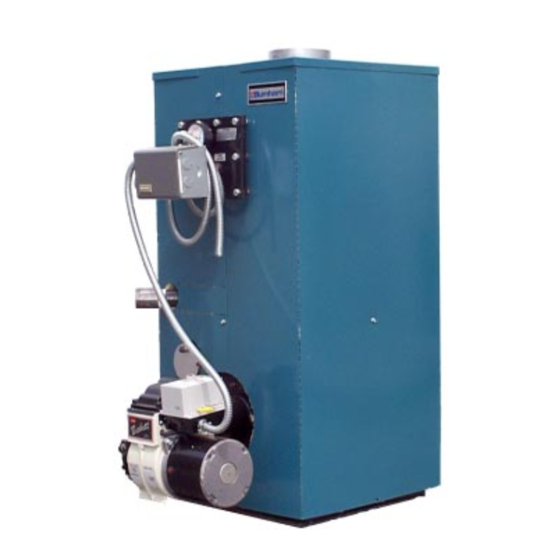
VII. System Start-Up ........30 III. Water Piping and Trim ...... 12 VIII. Service and Cleaning ......36 IV. Venting ..........18 IX. Repair Parts ........38 Electrical and Sequence of Operation 20 Figure 1: RSA Packaged Boiler (RSA85 / RSA135) - Page 6 Figure 1A: RSA Packaged Boiler (RSA170 / RSA285) M inim um Chimney Sizes Boiler Water Approx. B are Boiler Model Capacity S hipping In. x In. x Ft. In. (dia.) x Ft. A ssem bly Num ber Gallons Weight (height)
-
Page 7: Pre-Installation
1. Listed clearances comply with American National Standard ANSI/NFPA 31, Installation of Oil Burning Equipment. 2. RSA boilers can be installed in rooms with clearances from combustible material as listed above. Listed clearances can not be reduced for alcove or closet installations. - Page 8 PROVIDE AIR SUPPLY AND VENTILATION to than 50 ft /1000 BTU per hour then the space is considered a confined space. accommodate proper combustion. If natural ventila- tion is inadequate, provide a screened opening or duct from the boiler room to the outside. The opening or For boiler located in an unconfined space of a conven- duct must be sized so the boiler input will not exceed tionally constructed building, the fresh air infiltration...
-
Page 9: Knockdown Boiler Assembly
II. Knock-Down Boiler Assembly . REMOVAL OF BOILER. 1. Remove, all boiler to skid, hold down fasteners. Refer to Figure 3. 2. Carefully walk boiler to the edge of skid. Tilt the boiler back, allowing an edge to rest on the floor, and remove the skid. - Page 10 2. Bend jacket according to Figure 6. Starting from INSTALLATION OF BOILER CONTROLS the front, wrap the jacket around the boiler. Make sure that return pipe, observation port and shell 1. Install provided pressure/temperature gauge and extension fit proper into there corresponding immersion well into appropriate holes on tankless clearance holes.
- Page 11 Figure 6: RSA Jacket Assembly...
-
Page 12: Water Piping And Trim
III. Water Piping and Trim WARNING Failure to properly pipe boile r may re sult in i mproper ope ration and da mage to boiler or structure . Oxyge n c onta mination of boi ler water will cause corrosion of iron a nd s te el boiler c ompone nts , and can lead to boiler failure. - Page 13 Figure 7: Recommended Piping for Combination Heating and Cooling (Refrigeration) System C. Install Drain Valve in return piping. See Figures 8 . Install Pressure Relief Valve. See Figures 8 and 9. and 9. Pressure Relief Valve must be installed with spindle in the vertical position.
- Page 14 Figure 8: Recommended Boiler Piping for Circulator Zoned Heating Systems...
- Page 15 Figure 9: Boiler Piping for Zone Valve Zoned Heating Systems...
- Page 16 . CONNECT TANKLESS HEATER PIPING AS 2. TEMPERING OF HOT WATER — Installation of an automatic mixing valve will lengthen the SHOWN IN FIGURE 11. See Table 1 for Tankless Heater Rating. delivery of the available hot water by mixing some cold water with the hot.
- Page 17 Figure 11: Schematic Tankless Heater Piping Table 1: Tankless Heater Ratings S350 S375 Boiler Model PSID PSID RSA(H)85 & 110 3½ RSA110(H)125 & 135 3¼ 3¾ RSA125 & 135 3½ STD. #7524 OPT. #7530 Boiler Model PSID PSID RSA170 3¾...
-
Page 18: Venting
2. The RSA Series is designed to be vented into a cases, contribute to the condensing of small fireclay tile-lined masonry chimney or chimney amounts of water vapor in the chimney. - Page 19 Figure 12: Recommended Smokepipe Arrangement and Chimney Requirements Figure 13: Draft Regulator Locations...
-
Page 20: Electrical And Sequence Of Operation
V. Electrical DANGER Positively assure all electrical connecti ons are unpow ered before attempting installation or service of elec tric al components or connections of the boiler or bui lding. Lock out all ele ctrical boxes wi th pa dlock once power is turned off. WARNING Failure to properly wire electrical connections to the boiler may result in serious physical harm. - Page 21 Figure 14: “RSAL” Wiring Less Tankless, Single Circulator Figure 15: “RSAT” or “RSAR” Wiring with Tankless, Single Circulator...
- Page 22 Figure 16: Circulator Zoned Wiring for Honeywell R8888...
- Page 24 NOTICE The Honeywell R888 9 Control is ava ilable in two three (3) zone models and two four (4) zone models. Burnha m recommends using M ode l R88 89A for three (3) zone systems and Model R888 9B for four (4) zone systems. M odels R88 89C a nd R8889D have le ss load capac ity and may not operate w ith certain types of zone v alves.
- Page 25 NOTICE The Burnham EC50 00 Control includes a water temperature sensor. Mount this sensor to the sys te m s upply piping. 8. Burnham EC5000 Circulator Zoned System – Refer 9. Burnham EC5000 Zone Valve Zoned System – to Figure 19 of this manual for the electrical Refer to Figure 20 of this manual for the electrical diagram for this type of system.
- Page 26 Figure 19: Circulator Zoning with EC5000 Wiring Schematic...
-
Page 28: Oil Piping
VI. Oil Piping . General. . Single-pipe Oil Lines. 1. Use flexible oil line(s) so that burner can be 1. Standard burners are provided with single-stage removed without disconnecting the oil supply. 3450 rpm fuel units with the bypass plug removed for single-pipe installations. - Page 29 TABLE 2: SINGLE STAGE UNITS (3450 RPM) TABLE 3: TWO-STAGE UNITS (3450 RPM) TWO PIPE SYSTEMS TWO-PIPE SYSTEMS Maximum Length of Tubing Maximum Length of Tubing "H" +"R" (See Figure) Lift "H" Lift "H" "H" + "R" (See Figure) (See Figure) (See Figure) 3/8"...
-
Page 30: System Start-Up
VII. System Start-Up 10. Open isolation valve in boiler supply piping. . Verify that the venting, water piping, oil piping, and electrical system are installed properly. Refer to 11. Remove hose from bib cock. installation instructions contained in this manual. CONFIRM that the boiler and system have no water . - Page 31 Table 4: Beckett AFG, AF, & SF Burners Settings Firing Rate Hago Boiler Model (GPH) Nozzle Shutter Band Head (stop screw) Pump Pressure RSA85 .75 x 70B RSA110 1.10 .90 x 80B RSA125 1.25 1.0 x 80B RSA135 1.35 1.10 x 80B RSA170 1.70 1.65 80 A...
- Page 32 4. TURN “OFF” BURNER and remove pressure successful operation of the oil burner. The gauge. Install gauge port plug and tighten. Start selection of the nozzle supplied with the RSA burner again. boiler is the result of extensive testing to obtain the best flame shape and efficient combustion.
- Page 33 extreme case may become a fire hazard. oil is harder to atomize at the nozzle. Thus, the spray droplets get larger and the flame shape d. AIR LEAKS— Any such leaks should be gets longer. An outside fuel tank that is above repaired, as they may cause erratic burning of grade or has fuel lines buried in the ground the fuel and in extreme cases may become a fire...
- Page 34 4. CHECK LOW WATER CUTOFF (if so equipped). a. Adjust thermostat to highest setting. b. With boiler operating, open drain valve and slowly drain boiler. c. Burner should stop when water level drops below low water cutoff probe. Verify limit, a.
- Page 35 INSTALLATION INSTRUCTIONS FOR SHIELD REQUIRED FOR COMBUSTIBLE FLOOR This shield for combustible floors is intended for use only with the following Burnham oil-fired boilers: Use Part Number 6183504 for the following models: RSA(H)85 RSA(H)110 RSA(H)125 RSA(H)135 ADDS 4-3/16” TO BOILER HEIGHT...
-
Page 36: Service And Cleaning
Units should be cleaned at least once a year, preferably nance. at the end of each heating season. It is not necessary to remove burner to clean boiler. . Firetubes and Combustion Chamber. (See Figure 25) Brush, scrape, or vacuum from top. Figure 25: Cleaning of RSA Boiler... -
Page 37: Ix. Repair Parts
IX. Repair Parts All RSA Repair Parts may be obtained through your local Burnham Wholesale distributor. Should you require assistance in locating a Burnham distributor in your area, or have questions regarding the availability of Burnham products or repair parts, please contact your Burnham Regional Sales Office as listed below. - Page 38 REPAIR PARTS NOTE: When ordering parts always give the serial number and model number shown on the boiler. Also provide the name of the part(s) shown below:...
- Page 39 ITEM NO. QTY. DESCRIPTION PART NO. Wing Nut, 1/4 - 20 80860910 Washer, Flat 1/4 (SAE) 80860633 Canopy Assembly 6113509 1/2" Thick x 1" x 12-3/8" Cerafelt Strip 9206005 1/2" Thick x 1" x 13-3/8" Cerafelt Strip 9206005 Carriage Bolt, 1/4 - 20 x 3" Lg. 80860111 Turbulator 8113501...
- Page 40 NOTE: When ordering parts always give the serial number and model number shown on the boiler. Also provide the name of the part(s) shown below: Figure 27: RSA170-285 Boiler Repair Parts...
- Page 41 ITEM NO. DESCRIPTION PART NO. Jacket Top Panel Assembly 60435022 Canopy Assembly 6113510 ½" Thick x 1" x 23" C er afelt S trip 9206005 ½" Thick x 1" x 17" C er afelt S trip 9206005 Turbulator, See for Quantity 6113504 Tankless Heater Gasket 8036025...
- Page 42 ITEM DESCRIPTION PART NUMBER Jacket Top Panel 60435086 Jacket Wrap-A-Round Panel, RSA85/110 60435087 Jacket Wrap-A-Round P anel, RSA125/135 60435088 Temperature / P ressure Gauge 8056169U Honeywell L8148A1090 Hi-Limit Control 80160449U Honeywell L8124C1102 Limit Control 80160406 Observation Port Cover / Hardware 8026015 Burner Primary Control, R4184D1027 80160473...
- Page 43 SERVICE SCHEDULE DATE SERVICE PERFORMED...
- Page 44 BECKETT BURNER PARTS LIST FOR RSA SERIES STEEL BOILERS FOR REPLACEMENT OIL BURNER PARTS, CONTACT YOUR WHOLESALER OR THE BURNER MANUFACTURER: R. W. BECKETT CORP. 38251 CENTER RIDGE RD. P. O. BOX 1289 ELYRIA, OHIO 44036 1-800-645-2876 NOTE: When ordering parts always give the serial and model numbers shown on the boiler and burner. Also, provide the name of the part(s) and part(s) number as listed below.
- Page 45 Ordering Information for Quality Replacement Parts Figure 29: BECKETT AFG MODEL BURNER...
- Page 46 BECKETT BURNER PARTS LIST FOR RSA SERIES STEEL BOILERS FOR REPLACEMENT OIL BURNER PARTS, CONTACT YOUR WHOLESALER OR THE BURNER MANU- FACTURER: R. W. BECKETT CORP. 38251 CENTER RIDGE RD. P. O. BOX 1289 ELYRIA, OHIO 44036 1-800-645-2876 Boiler Model...
- Page 47 Ordering Information for Quality Replacement Parts Figure 30: BECKETT AF and SF MODEL BURNERS...