
Related Manuals for Hensel EXPERT D 500

Summary of Contents for Hensel EXPERT D 500
- Page 1 / / E X P E R T D 5 0 0 / D 1 0 0 0 C o m p a c t f l a s h u n i t U S E R M A N U A L / /...
- Page 2 Made in Germany performing light AUDIO SLAVE TEST freemask FULL PROP HENSEL Profoto Air...
- Page 3 F3 F4 Strobe Wizard Plus / freemask P2 P3 P4 P1 P2 P3 P4 Profoto Air Remote Profoto Air Sync...
- Page 4 E-mail: info@hensel.de Internet: http://www.hensel.de © HENSEL-VISIT GmbH & Co. KG, 2013 Distribution and reproduction of this documentation is not permitted unless specifically authorized. In case of violation, payment of damages will be due. All rights reserved, including rights created by patent grant, or registration of a utility model or design (ISO 16016).
-
Page 5: Preface
1 Preface Dear photographer, By purchasing the Hensel-Visit compact flash unit Expert D 500/1000, you have selected a high-quality and high performance product. Below, we want to give you some details and hints on how to use this unit. These will ensure successful and productive work with it in the coming years. -
Page 6: Table Of Contents
User Manual Expert D 500/1000 2 Content 1 Preface ................5 2 Content ................6 3 Safety instructions ............8 4 General ................11 Description ...............11 Scope of delivery ............11 5 Technical data ...............12 6 Summary of control elements .........14 7 Initial use ...............15 Acclimatization ............15... - Page 7 User Manual Expert D 500/1000 Summary of control elements ........24 Setting transmitter .............24 Setting receiver ............25 Output adjustment ............25 Switching the modeling light ........25 10 Operation with freemask ..........26 Settings for the freemask method .......26 11 Operation with Profoto Air ..........28 Basic functions ............28...
-
Page 8: Safety Instructions
Normal use The compact flash unit Expert D 500/1000 is intended for professional use inside the studio. It is only to be used with the accessories described in this manual and approved by Hensel- Visit. - Page 9 Use the tilt bracket’s safety screw 11 and secure the device additionally with a safety rope. Suitable safety ropes can be purchased from Hensel-Visit, see „14 Accessories“ on page 40. HENSEL-VISIT GmbH & Co. KG...
- Page 10 This means touching the device could pose a life-threatening danger. Halogen lamps and flash tubes may burst and must only be operated with properly mounted Hensel safety dome. ATTENTION! Contact with capacitor voltage can pose mortal danger.
-
Page 11: General
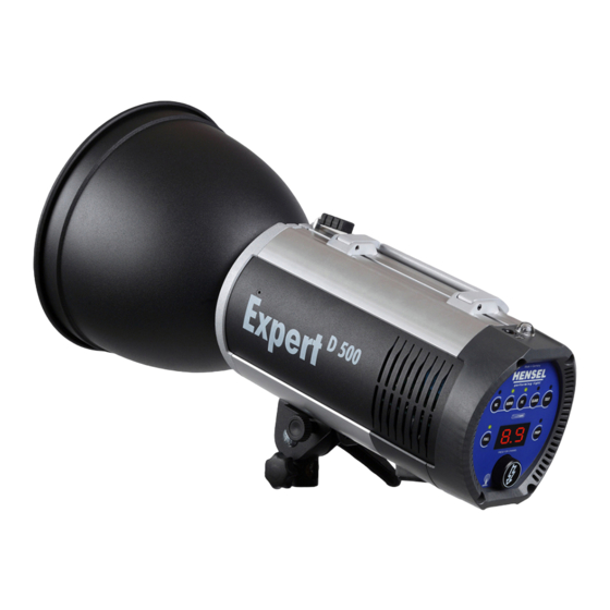
User Manual Expert D 500/1000 4 General Description The Expert D 500/1000 is a powerful compact flash unit. Ext- remely fast flash recycle times and short flash duration hallmark this unit which can be used worldwide thanks to mulivoltage. A... -
Page 12: Technical Data
User Manual Expert D 500/1000 5 Technical data Unit series/unit type Expert D 500 Expert D 1000 Listed performance output: 500 J 1000 J Lead aperture 100 ASA, t 1 m = 90 0/10 1 m = 128 0/10 1/60, 12“ reflector, 100%... - Page 13 - Glass safety dome: - Display: 7-segment for flash energy/daily flash counter/channel display/auto- red/Error code - Control surface: imprinted foil with keys, fluorescent, Hensel user logic Code no.: 8350 8360 Technical modifications excepted. The listed data are standard values which may deviate depending on component tolerances.
-
Page 14: Summary Of Control Elements
User Manual Expert D 500/1000 6 Summary of control elements 1 ..Slave on/off / PM mode on/off SLAVE 2 ..Flash readiness indicator 3 ..Flash trigger TEST 4 ..Modeling light proportional PROP 5 ..Display for set energy/channel indicator/flash counter 6 .. -
Page 15: Initial Use
User Manual Expert D 500/1000 7 Initial use ATTENTION! Please make sure that the unit is not connected to a power sup- ply when preparing for initial use. Acclimatization When relocating the compact flash unit from and to locations with substantial temperature differences, place the unit in the surroundings where it is to be used and leave it there for some time. -
Page 16: Inserting Flash Tube
User Manual Expert D 500/1000  Then use gentle pressure to insert the safety dome first into the second spring and then into the third spring until it locks into place. Removal  Tilt the safety dome slightly so that it is released one by one from the mounting springs. -
Page 17: Power Supply
The type label is located at the bottom of the housing. The com- pact flash Expert D 500/1000 is solely approved for use with 115 V - 230 V / 50-60 hz operation. - Page 18 Fuse protection, modeling light The safety fuse 7 ensures the protection of the modeling light. The compact flash unit Expert D 500/1000 is protected by a 4 A Fuse which reacts quickly (F 4 A H). The listed safety values apply when the unit is used with a 300 W halogen lamp.
-
Page 19: Operation
User Manual Expert D 500/1000 8 Operation Switch on/off The main switch 6 switches the compact flash unit on or off. The unit is ready to flash as soon as the ready indicator 2 lights up. ATTENTION! The power switch must be accessible and operational at all times. -
Page 20: Performance Output Adjustment
2 lights up to indicate restored flash readiness. Flash Check The Expert D 500/1000 is equipped with a visual flash readi- ness indicator called Flash Check. When this function is acti- vated, the modeling light shuts off after flashing and turns on again when the flash readiness is restored. -
Page 21: Test Flash
User Manual Expert D 500/1000 Test flash The key TEST 3 lets you trigger a test flash manually. Holding down the key results in the fastest possible sequence of flashes. Flash readiness After switching the unit on, after flashing, and after adjusting the flash output, flash readiness is indicated on a green LED 2 located above the TEST key 3. -
Page 22: Pm Mode (In Connection With Power Max L)
Synchronization via radio remote trigger The optional radio remote triggers Strobe Wizard Plus, free- mask and Hensel Profoto Air are used to conveniently synchro- nize the camera and flash unit via radio remote control. See „14 Accessories“ on page 40. - Page 23 ATTENTION! Expert D flash units prior to serial number 1303H0030101340 (Expert D 500) and 1303H0030100461 (Expert D 1000) do not function in connection with the Power Max L and need a new operating software. Please contact your Hensel service at the Wuerzburg headquar- ters and have the update done there.
-
Page 24: Operation Strobe Wizard Plus
User Manual Expert D 500/1000 9 Operation Strobe Wizard Plus Radio triggering The compact flash unit has a built-in radio receiver that can be used for flash triggering. Radio remote This radio connection also allows you to remotely control the control modeling light. -
Page 25: Setting Receiver
User Manual Expert D 500/1000 Â Set the channel selection switch F5 to channel 1, 2 or 3. - or - Â Select the switch position ALL when all channels are to be controlled. Setting receiver The key RC 18 on the flash head is used to activate the radio receiver and to set the channel. -
Page 26: Operation With Freemask
User Manual Expert D 500/1000 10 Operation with freemask The transmitter „freemask“ has all the functions of the Strobe Wizard Plus and is operated the same way. Output adjustment via the transmitter can only be done in the „C“-channels, not in the „F“... - Page 27 Â Set the compact flash unit for the mask on „F“ channels (F1, F2, F3). Note: In this case, the slave of the Expert D 500/1000 needs to be switched off with the SLAVE key 1 to prevent triggering the first group of flashes. All other slaves can be switched on.
-
Page 28: Operation With Profoto Air
Basic functions Channels Profoto Air Sync/Remote units transmit via 8 different channels. The Expert D 500/1000 has 8 Profoto channels. Work at 8 different stations is possible without interfering with each other. Groups Additionally, the Profoto Air Remote and the Expert D 500/1000 include the option of assigning the units to be triggered to up to 6 groups and then control these jointly. -
Page 29: Summary Of Control Elements
User Manual Expert D 500/1000 Summary of control elements P1 ..Channel selection key CHANNEL P2 ..Mode transmitter/receiver MODE P3 ..Test flash flash/camera TEST P4 ..On/off key ON P5 ..Flash output increase ENERGY + P6 ..Flash output reduction ENERGY - P7 .. -
Page 30: Remote Trigger
 Press the channel selection key P1 until the desired channel 1-8 is indicated on the LED bar. Expert D The Profoto Air channels of Expert D 500/1000 are desig- 500/1000 nated with P1- P8 and are shown on display 5, e.g. P .1A for channel 1 and group A. - Page 31 User Manual Expert D 500/1000 Setting group The group setting lets you combine individual flash heads. This allows you to jointly control the settings of the flash heads con- tained in this group. Triggering of the flash heads is done via the channel assign- ment.
-
Page 32: Remote Control
User Manual Expert D 500/1000 Remote control Setting power output The keys P5 +and P6 – are used for adjusting the flash output ENERGY of the controlled flash unit. Briefly pressing the key ad- justs the power in steps of 0.1 f-stops, pressing the key longer (>... -
Page 33: Maintenance
The compact flash unit must be switched off and disconnected from the power supply before doing any maintenance work to it. The compact flash unit Expert D 500/1000 requires little user maintenance. To guarantee the electrical safety, the outside of the unit must be cleaned regularly from dust and dirt. -
Page 34: Updating Software
User Manual Expert D 500/1000 How to replace a fuse: Â Open the safety drawer 7 with a small screwdriver and pull it out. Note: The drawer can only be pulled out approximately 1 cm. Inside the drawer are two fuses. The rear fuse a is an active fuse, the front fuse b is a spare fuse. -
Page 35: Replacing Flash Tube
User Manual Expert D 500/1000 Replacing flash tube The compact flash unit’s flash tube is plug-in. In case of a de- fect, it can be replaced by the user. ATTENTION! Switch off the unit and wait at least 15 minutes for the capacitor voltage to deplete before replacing the flash tube. -
Page 36: Replacing Modeling Light
 Pull the flash tube out again approximately 0.5 mm so that the glass body can expand upon warming.  Wrap the wire B onto the connecting pin C. Suitable flash tubes for compact flash unit Expert D 500/1000, see chapter „14 Accessories“ on page 40. Replacing modeling light The halogen lamp of the compact flash unit’s modeling light is... -
Page 37: Error Messages
User Manual Expert D 500/1000 Error messages In case of an error, an error code is shown in display 5. In this case proceed as follows: Â Switch off the unit. Â Wait a few seconds. Â Switch the unit on again. -
Page 38: Warranty
Warranty The warranty period for the compact flash unit Expert D 500/1000 depends on the country of delivery. You can obtain information pertaining to warranty periods on the Internet pages of the distributing companies. Normal usage, meeting the safety requirements in the inst- ruction manual, and adhering to the information therein are prerequisites for this warranty. -
Page 39: Customer Service Points
Fax: +49 (0)931 278 815 0 E-Mail: info@hensel.de Service points listed in the Internet Additional national and international service and distribution addresses can be found on the web page of Hensel-Visit GmbH & Co. KG: www.hensel.de HENSEL-VISIT GmbH & Co. KG... -
Page 40: Accessories
Profoto / Hensel Air Remote code no.: 3966 Additional accessories Safety rope code no.: 7690 Sync cord, various lengths Umbrellas Additional information about accessories can be found on the Internet page of HENSEL-VISIT GmbH & Co. KG: www.hensel.de HENSEL-VISIT GmbH & Co. KG... -
Page 41: Subject Index
User Manual Expert D 500/1000 15 Subject index APD function 20 Output adjustment 20, 25, 26 Autored 12, 19 Power supply 10, 15, 17, 33, 36 Control elements 14, 24, 30 Profoto Air 22, 30 Radio remote trigger 22 Daily flash counter 12, 21... -
Page 42: Eu Declaration Of Conformity
User Manual Expert D 500/1000 16 EU declaration of conformity about electro-magnetic compatibility and electrical safety HENSEL-VISIT GmbH & Co. KG... - Page 43 User Manual Expert D 500/1000 Notes HENSEL-VISIT GmbH & Co. KG...
Need help?
Do you have a question about the EXPERT D 500 and is the answer not in the manual?
Questions and answers