Table of Contents
Advertisement
Available languages
Available languages
Quick Links
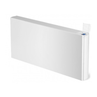
VIDO - HEATING & COOLING
INSTALLATION, OPERATING, MAINTENANCE & AFTER SALES MANUAL
VIDO - CHAUFFER & REFROIDIR
MANUEL D'INSTALLATION, D'UTILISATION ET DE SERVICE
VIDO - VERWARMEN & KOELEN
INSTALLATIE-, GEbRUIKERS- EN SERVICEHANDLEIDING
Product Serial Number:
Please leave this manual with the end user.
Part Number: 1370071
Advertisement
Chapters
Table of Contents

Related Manuals for RADSON Vido Series


Summary of Contents for RADSON Vido Series
- Page 1 VIDO - HEATING & COOLING INSTALLATION, OPERATING, MAINTENANCE & AFTER SALES MANUAL VIDO - CHAUFFER & REFROIDIR MANUEL D’INSTALLATION, D’UTILISATION ET DE SERVICE VIDO - VERWARMEN & KOELEN INSTALLATIE-, GEbRUIKERS- EN SERVICEHANDLEIDING Product Serial Number: Please leave this manual with the end user. Part Number: 1370071...
-
Page 2: Table Of Contents
Contents Introduction Warnings & Safety Measures Heating System Design Unit Selection/Sizing Location Preparation Fixing Water Connection Electrical Connection 10.0 Commissioning Procedure 11.0 Technical Data 12.0 Control System Set-up and Operating Instruction 12.1 Unit Operation 12.2 Operating Modes 12.3 Installer’s Set-up Parameters 12.4 building Management System Input Set-up 12.5... -
Page 3: Introduction
1.0 Introduction This heater/cooler fan convector is designed for use on The unit is fitted with a washable air filter that can be easily central heating systems or heating and cooling systems in removed for cleaning (see Section 14). homes and commercial environments. Models are available A range of accessories are available for this product including with 2 and 4-pipe connections. -
Page 4: Unit Selection/Sizing
3.0 Heating System Design (continued...) Note: Pressure independent balancing and connection sets are available for this product as an accessory. These valve kits will maintain the flow in the unit to the required levels. (See Section 15). NB: Pipes should be sized using flow rate and pressure losses. 15mm No microbore pipework 4.0 Unit Selection/Sizing... -
Page 5: Preparation
6.0 Preparation Before proceeding with the installation, remove the carton lid, unpack the contents carefully and check against the checklist below: 1. Heater/Cooler unit (chassis) 2. Outer casing 3. Warranty card 4. Instruction manual 5. Fixing kit Check contents for concealed shipping damage. Tools required: Mounting dimensions Dimensions (mm) -
Page 6: Fixing
7.0 Fixing Dimensions (mm) Dimensions (mm) NOTE: Do not replace outer cover until connection to system and connection to electrical supply has been completed. -
Page 7: Water Connection
8.0 Water Connection Connect the unit to the flow and return pipes, pipework can be and can be removed by unscrewing the two bracket fixing screws. routed from the floor or through the wall at the back of the unit. Removal of this component will aid pipework fitting when the (See options below). - Page 8 8.0 Water Connection (continued...) Dimensions 2-pipe Dimensions (mm) Dimensions 4-pipe COOL OUT HOT OUT HOT IN COOL IN h > 150 Dimensions (mm)
- Page 9 8.0 Water Connection (continued...) How to bleed/vent Condensate drain connection Spiggot size 15mm O/D Connecting tube >15mm I/D Ensure all water fittings are secure before filling the system. should be connected to a 15mm drain pipe. Fill the system, open the valves fully and check pipe connections Alternatively a condensate disposal pump is available as an for leaks and vent the heat exchanger.
-
Page 10: Electrical Connection
9.0 Electrical Connection WArNiNg: This appliance must be earthed. The electrical installation must comply with local or national wiring regulations. l The electrical installation of this appliance should be carried l Connect the live and neutral wires to the power board out by a qualified electrician in accordance with current terminal connections, and the earth wire to the chassis earth regulations. - Page 11 9.0 Electrical Connection (continued...) Refer to wiring diagrams below and on page 12-13. 3. Routing cable After making the electrical connections replace the side cover to the control box. 2-pipe 0 valve CONTROL BOARD Supply 230V POWER 50Hz BOARD WATER SENSOR 2-PIPE SENSOR TRANSFORMER...
- Page 12 2-PIPE 1 VALVE 9.0 Electrical Connection (continued...) if you are using the valves please refer to 2-pipe 1 valve the Valve Kit instructions. Input* 230V 50Hz CONTROL 24V 50Hz BOARD 24V DC Supply 230V POWER 50Hz BOARD WATER SENSOR 2-PIPE SENSOR TRANSFORMER *Voltage free contacts - 230V 50Hz supply needed accross CO+ and COM- to energise actuator.
- Page 13 9.0 Electrical Connection (continued...) if you are using the valves please refer to 4-pipe 2 valve the Valve Kit instructions. Input* 230V 50Hz CONTROL POWER BOARD BOARD 24V 50Hz 24V DC COLD Supply 230V 50Hz WATER SENSOR 4-PIPE COOLING ONLY WATER SENSOR 2-PIPE SENSOR...
-
Page 14: Commissioning Procedure
10.0 Commissioning Procedure 1. l Fill and vent the system. l Open all valves fully and vent air from the heat exchanger. l Check for leaks at pipe connections. 2. l Refit the outer casing and secure with the 2 screws. l Switch on the electrical supply. -
Page 15: Technical Data
11.0 Technical Data Performance Data 2-Pipe Heat Output (Watts) Cooling (Watts) Model Condition 7-12-27 Flow Speed ∆T20 ∆T25 ∆T30 ∆T35 ∆T40 ∆T45 ∆T50 (l/h) Total Sensible Normal 1146 1355 1567 1781 1997 Medium 1260 1537 1817 2101 2388 2678 1126 600x800 Boost 1360... -
Page 16: Electrical Data
11.0 Technical Data (continued...) Dimensions Sound Levels Sound Pressure (dBA) (at 2.5m) Nominal Height Depth Length Model Model (mm) (mm) (mm) Normal Medium Boost 600x800 600x8000 24.8 37.7 47.9 600x1000 1000 600x1000 35.8 47.9 600x1200 1200 600x1200 40.5 51.7 600x1400 1400 600x1400 24.9... -
Page 17: Control System Set-Up And Operating Instruction
12.0 Control System Set-up and Operating Instruction General Description Additional functions are available if necessary from the Full operating mode menu. The electronic control system on this unit provides a wide range of A range of additional parameters and features can be changed or options that can be selected according to system complexity and activated in a further set up menu should these be required. - Page 18 12.1 Unit Operation (continued...) Easy Mode Display Heating indicator Cooling indicator Temperature symbol – when this is displayed the current room temperature is displayed Fan speed symbol (fan blades will rotate when active) Comfort setting Power (on/off) Clock setting Room temperature Time Day of the week Keys:...
-
Page 19: Operating Modes
12.2 Operating Modes Use ( ) and ( ) keys to choose from the following parameters. A function is selected when the icon is surrounded by Availability Function Description Adjustment Easy Full Control Operation Setup Control Operation Setup The unit must be programed for operation Scroll to the Fixed Fan mode , and then press in heating only, cooling only or heating and... -
Page 20: Installer's Set-Up Parameters
12.3 Installer’s Set-up Parameters The various parameters that can be defined by the installer are Press (OK) to toggle the parameter setting or edit the value. If the value starts to blink, use (+) and (-) keys to adjust the value. shown in the table below. -
Page 21: Program Mode
12.5 Program Mode Program Menu A quantity of 9 built-in (P1 - P9) and 4 user defined (U1 - U9) timed program options are available to choose from. Each day is divided into 24 one hour periods operating in either Comfort setting (21°C default) or Night set-back setting (19°C default). -
Page 22: Troubleshooting
13.0 Troubleshooting Please follow the troubleshooting guide below before calling incorrectly set, that there is no electrical supply to the unit or that for assistance. It is important to make sure that an apparent the unit is incorrectly set. problem with this unit is not the result of system controls being Problem Possible Causes remedy... -
Page 23: Maintenance
14.0 Maintenance Disconnect from the power supply before carrying out maintenance work. Maintenance should be restricted to occasional removal of dust and lint around the unit. The outer surface may be wiped over with warm water and mild detergent taking care to avoid water entering the grille areas. -
Page 24: Spare Parts
16.0 Spare Parts Description Model item Control Bezel 600x800 600x1000 Casing 600x1200 600x1400 600x1600 Branding Clip Heat Exchanger Not available as a spare Power Board 2-Pipe Control Board 4-Pipe Transformer 600x800, 600x1000 600x1200, 600x1400, Motor 600x1600 600x800 600x1000 Filter 600x1200 600x1400 600x1600 Secondary... - Page 25 VIDO - CHAUFFER & REFROIDIR MANUEL D’INSTALLATION, D’UTILISATION ET DE SERVICE...
- Page 26 Contenu Introduction Consignes de sécurité Conception système de chauffage Sélection/Dimensionnement des unités Emplacement Préparation Montage Raccordement hydraulique Raccordement électrique 10.0 Mise en service 11.0 Données techniques 12.0 Réglage commande et fonctions 12.1 Fonctionnement 12.2 Modes de fonctionnement 12.3 Paramètres niveau installateur 12.4 Réglages système de gestion technique de bâtiment (GTb) 12.5...
-
Page 27: Introduction
1.0 Introduction Ce ventilo-convecteur peut être incorporé dans une installation L’appareil est équipé d’un filtre à air lavable lequel est détachable de chauffage central ou dans un système de climatisation de aisément pour le nettoyage (voir section 14). logements familiaux et d’espaces commerciaux. Disponible en Un large éventail d’accessoires est disponible, y compris vannes de version à... -
Page 28: Sélection/Dimensionnement Des Unités
3.0 Conception système de chauffage (suite...) Note: Les accessoires de ce produit comportent des kits de raccordement et réglage et d’équilibrage insensibles à la pression. Ces vannes maintiennent le débit dans l’unité au niveau requis. Veuillez consulter la section 15. NB: If faut dimensionner la tuyauterie à... -
Page 29: Préparation
6.0 Préparation Avant d’entamer l’installation, veuillez enlever l’emballage de carton et désemballer prudemment les divers composants. Contrôlez le contenu à l’aide de la liste ci-dessous: 1. Appareil de chauffage/ refroidissement (châssis) 2. Manteau 3. Carte de garantie 4. Manuel d’utilisation 5. -
Page 30: Montage
7.0 Montage Dimensions (mm) Dimensions (mm) NOTE: Avant de remonter le manteau, effectuer tous les raccordements hydrauliques et électriques. -
Page 31: Raccordement Hydraulique
8.0 Raccordement hydraulique Raccordez l’unité aux conduites de départ et de retour. Vous pouvez l’enlever en dévissant les deux vis de l’étrier de fixation. En ôtant faire passer les conduites par le sol ou à travers le mur à l’arrière de ce composant, l’installation des conduites passant du sol, se fera l’unité... - Page 32 8.0 Raccordement hydraulique (suite...) Dimensions 2 tubes Dimensions (mm) Dimensions 4 tubes SORTIE FROID SORTIE CHALEUR ENTRÉE CHALEUR ENTRÉE FROID Dimensions (mm)
- Page 33 8.0 Raccordement hydraulique (suite...) Purger/désaérer Raccordement évacuation condensat Dimension bout mâle Diamètre externe 15mm Tuyau de raccordement Diamètre interne >15mm Avant de remplir le système, assurez-vous que tous les réglementations locales en vigueur. raccordements hydrauliques sont étanches. L’appareil a été équipé d’un bac de récupération du condensat. Remplissez le système, ouvrez entièrement les vannes et contrôlez Connectez-le à...
-
Page 34: Raccordement Électrique
9.0 Raccordement électrique AVErTiSSEMENT: il faut que cet appareil soit mis à la terre. il faut que l’installation électrique soit effectuée conformément aux réglementations locales et nationales en vigueur. l L’installation électrique de cet appareil ne peut être réalisée que l Connectez le fil conducteur et le neutre aux bornes du tableau par un électricien qualifié... - Page 35 9.0 Raccordement électrique (suite...) Veuillez consulter les schémas de câblage ci-dessous et aux pages 3. Câblage 12-13. Après avoir effectuées les connexions électriques, remontez le couvercle du tableau de commande. Connexion GTB Connexion vanne de réglage Tension Terre Neutre Passe-câbles 2 tubes 0 vannes TABLEAU DE COMMANDE...
- Page 36 2-PIPE 1 VALVE 9.0 Raccordement électrique (suite...) Si vous utilisez nos vannes, veuillez consulter les 2 tubes instructions ajoutées au kit. 1 vanne TABLEAU DE Input* 230V 50Hz Entrée* 230V 50Hz CONTROL 24V 50Hz COMMANDE BOARD 24V 50Hz 24V DC 24V DC Alimentation Supply 230V...
- Page 37 9.0 Raccordement électrique (suite...) Si vous utilisez nos vannes, veuillez consulter les 4-pijps 2 afsluiters ter 4 tubes instructions ajoutées au kit. 2 vannes Input* 230V 50Hz TABLEAU TABLEAU DE CONTROL POWER Entrée* 230V 50Hz BOARD BOARD 24V 50Hz ÉLECTriQUE COMMANDE 24V 50Hz 24V DC...
-
Page 38: Mise En Service
10.0 Mise en service 1. l Remplir et désaérer le système. l Ouvrir entièrement les vannes et purger l’air de l’échangeur de chaleur. l Contrôler les raccordements tubes pour voir s’il reste des fuites. 2. l Replacer et fixer le manteau à l’aide des 2 vis. l Mettre sous tension. -
Page 39: Données Techniques
11.0 Données techniques Puissance 2 tubes Puissance calorifique (Watt) Puissance frigorifique (Watt) Vitesse de Model Condition 7-12-27 Débit ventilation ∆T20 ∆T25 ∆T30 ∆T35 ∆T40 ∆T45 ∆T50 (l/h) Total Sensible Normal 1146 1355 1567 1781 1997 Medium 1260 1537 1817 2101 2388 2678 1126... - Page 40 11.0 Données techniques (suite...) Dimensions Niveau sonore Pression acoustique (dBA) (op 2,5m) Hauteur Profondeur Longueur Modèle Modèle nominale (mm) (mm) (mm) Normal Medium Boost 600x800 600x800 24,8 37,7 47,9 600x1000 1000 600x1000 35,8 47,9 600x1200 1200 600x1200 40,5 51,7 600x1400 1400 600x1400 24,9...
-
Page 41: Réglage Commande Et Fonctions
12.0 Réglage commande et fonctions Généralités Le ‘Full mode’ offre encore des fonctions supplémentaires. La commande électronique de cet appareil vous offre tant d’options Le cas échéant, des paramètres et des fonctions additionnels suivant la conception du système et les exigences de l’utilisateur. peuvent être modifiés ou activés dans un menu suivant. - Page 42 12.1 Fonctionnement (suite...) Affichage Easy Mode Indicateur chauffage Indicateur refroidissement Température – si cet icône apparaît à l’écran, la température ambiante actuelle est affichée Vitesse ventilateur (les aubes tournent lorsque le ventilateur est activé) Mode confort Marche/arrêt Réglage horloge Température ambiante Heure Jour de la semaine Touches:...
-
Page 43: Modes De Fonctionnement
12.2 Modes de fonctionnement Lorsqu’un icône reçoit un cadre illuminé , la fonction en question Utilisez les touches de navigation ( ) et ( ) pour faire votre a été sélectionnée. choix des paramètres suivants. Présent Fonction Description réglage Easy Full Réglage mode de fonctionnement Réglage mode de fonctionnement... -
Page 44: Paramètres Niveau Installateur
12.3 Paramètres niveau installateur Le tableau ci-dessous montre les divers paramètres à régler par Appuyez (OK) pour modifier le paramètre ou ajuster sa valeur. l’installateur. Quand la valeur clignote, celle-ci peut être ajustée à l’aide des touches (+) et (-). Une fois la valeur ajustée correctement, vous L’accès au menu paramétrage se fait en défilant à... -
Page 45: Programmation
12.5 Programmation Menu programmation Défilez à l’aide des touches (+) et (-) pour choisir l’option souhaitée. Vous avez le choix de 9 programmes préréglés (P1 - P9) et 4 programmes personnels (U1 – U4) de l’utilisateur. Chaque jour est divisé en 24 périodes d’une heure, tant pour le mode confort (par défaut 21°C), que pour le mode abaissement nocturne (par défaut 19°C). -
Page 46: En Cas De Dérangement
13.0 En cas de dérangement Avant d’appeler de l’assistance technique, veuillez contrôler les incorrectement, d’une coupure de courant ou d’un appareil réglé points suivants. Il est important de s’assurer qu’un problème de manière inexacte. apparent n’est pas le résultat d’une commande réglée Problème Causes probables remède... -
Page 47: Entretien
14.0 Entretien Débranchez toujours l’alimentation électrique avant d’effectuer de l’entretien. L’entretien se limite à l’élimination occasionnelle de poussière et de peluches autour de l’appareil. Le manteau peut être lavé à l’eau tiède avec un détergent doux. Faites attention à ce que l’eau n’entre pas les grilles. -
Page 48: Pièces Détachées
16.0 Pièces détachées Description Modèle item Couvercle commande Tous 600x800 600x1000 Manteau 600x1200 600x1400 600x1600 Branding Clip Tous Échangeur de chaleur Pas disponible comme pièce détachée Tableau électrique Tous 2 tubes Tableau de commande 4 tubes Transformateur Tous 600x800, 600x1000 600x1200, 600x1400, Moteur 600x1600... - Page 49 VIDO - VERWARMEN & KOELEN INSTALLATIE-, GEbRUIKERS- EN SERVICEHANDLEIDING...
- Page 50 Inhoud Inleiding Veiligheidsvoorschriften Ontwerp verwarmingssysteem Selectie/Dimensionering units Plaatsing Voorbereiding Montage Hydraulische aansluiting Elektrische aansluiting 10.0 Inbedrijfstelling 11.0 Technische gegevens 12.0 Instelling bediening en functies 12.1 Werking 12.2 Functies 12.3 Parameterinstellingen op installateursniveau 12.4 Instellingen voor een gebouwbeheersysteem (GbS) 12.5 Programmeermodus 13.0 bij storing 14.0...
-
Page 51: Inleiding
1.0 Inleiding Deze ventiloconvector kan ingepast worden in een centrale Wij bieden een ruime waaier toebehoren aan voor dit verwarmingsinstallatie of in een klimatisatiesysteem in product, inclusief regelventielen en condensatiepompen voor gezinswoningen en commerciële ruimtes. Verkrijgbaar in 2- en in koelinstallaties (zie hoofdstuk 15). -
Page 52: Selectie/Dimensionering Units
3.0 Ontwerp verwarmingssysteem (vervolg...) Noot: Bij de toebehoren voor dit product vindt u druk- gecompenseerde aansluit- en inregelsets. Deze afsluiters zorgen er ook voor dat het debiet in de unit op het vereiste niveau blijft. Raadpleeg het hoofdstuk 15. NB: Dimensioneer de leidingen aan de hand van het debiet en de drukverliezen. 15mm Geen microbore leidingmateriaal 4.0 Selectie/Dimensionering units... -
Page 53: Voorbereiding
6.0 Voorbereiding Voor u met de installatie begint, verwijdert u de kartonnen verpakking en pakt u alles voorzichtig uit. Controleer de inhoud aan de hand van onderstaande checklist: 1. Verwarmings-/koeltoestel (chassis) 2. Mantel 3. Garantiekaart 4. Gebruiksaanwijzing 5. Bevestigingskit Controleer de inhoud op verborgen transportbeschadigingen. Benodigd gereedschap: Montage-afmetingen Afmetingen (mm) -
Page 54: Montage
7.0 Montage Afmetingen (mm) Afmetingen (mm) NOOT: Sluit het toestel eerst hydraulisch en elektrisch aan vooraleer u de mantel terugplaatst. -
Page 55: Hydraulische Aansluiting
8.0 Hydraulische aansluiting Sluit de unit aan op de aanvoer- en retourleidingen. U kan warmtewisselaaraansluitingen gemonteerd is, overbodig. Deze kan de leidingen door de vloer laten lopen of door de muur aan u wegnemen door de twee schroeven van de bevestigingsbeugel de achterkant van de unit (zie mogelijke opties hieronder). - Page 56 8.0 Hydraulische aansluiting (vervolg...) Afmetingen 2-pijps Afmetingen (mm) Afmetingen 4-pijps KOUDE UIT WARMTE UIT WARMTE IN KOUDE IN Afmetingen (mm)
- Page 57 8.0 Hydraulische aansluiting (vervolg...) Aftappen/ontluchten Aansluiting condensafvoer Afmeting tap buitendiameter 15 mm Aansluitslang binnendiameter > 15 mm Controleer of alle hydraulische aansluitingen stevig vastzitten Het toestel is binnenin uitgerust met een lekbak voor opvang van vooraleer u het systeem gaat vullen. het condenswater.
-
Page 58: Elektrische Aansluiting
9.0 Elektrische aansluiting WAArSCHUWiNg: Dit toestel moet geaard worden. De elektrische installatie moet conform de lokale en nationale reglementeringen uitgevoerd worden. l De elektrische installatie van dit apparaat moet uitgevoerd l Sluit de spanning en de nulleider aan op de klemmen op het worden door een gekwalificeerd elektromonteur conform de elektrisch bord en de aardingskabel op de aardingsklem van het geldende reglementeringen. - Page 59 9.0 Elektrische aansluiting (vervolg...) Raadpleeg de bedradingsschema’s onderaan en op pagina 12-13. 3. Kabelloop Nadat u alles elektrisch aangesloten heeft, plaatst u het deksel van het bedieningspaneel terug. Aansluiting GBS Aansluiting regelventiel Spanning Aarding Nulleider Kabel- doorvoeren 2-pijps 0 afsluiters BEDIENINGSBORD CONTROL BOARD...
- Page 60 2-PIPE 1 VALVE 9.0 Elektrische aansluiting (vervolg...) Wanneer u de afsluiter gebruikt, gelieve dan de 2-pijps 1 afsluiter bij de kit geleverde instructies te raadplegen. BEDiENiNgSBOrD Input* 230V 50Hz input* 230V 50Hz CONTROL 24V 50Hz BOARD 24V 50Hz 24V DC 24V DC Voeding 230V Supply 230V...
- Page 61 9.0 Elektrische aansluiting (vervolg...) Wanneer u de afsluiter gebruikt, gelieve dan de 4-pijps 2 afsluiters ter 4-pijps 2 afsluiters bij de kit geleverde instructies te raadplegen. Input* 230V 50Hz ELEKTriSCH BEDiENiNgSBOrD CONTROL POWER input* 230V 50Hz BOARD BOARD 24V 50Hz BOrD 24V 50Hz 24V DC...
-
Page 62: Inbedrijfstelling
10.0 Inbedrijfstelling 1. l Vul en ontlucht het systeem. l Open alle kranen volledig en ontlucht de warmtewisselaar. l Controleer de leidingaansluitingen op lekken. 2. l Plaats de mantel terug en maak vast met de 2 schroeven. l Schakel de stroomtoevoer aan. l Controleer de werking van de unit volgens de stappen in de handleiding. -
Page 63: Technische Gegevens
11.0 Technische gegevens Vermogen 2-pijps Verwarmingsvermogen (Watt) Koelvermogen (Watt) Ventilator Model Conditie 7-12-27 Debiet snelheid ∆T20 ∆T25 ∆T30 ∆T35 ∆T40 ∆T45 ∆T50 (l/h) Totaal Voelbaar Normaal 1146 1355 1567 1781 1997 Medium 1260 1537 1817 2101 2388 2678 1126 600x800 Boost 1360 1733... - Page 64 11.0 Technische gegevens (vervolg...) Afmetingen Geluidsniveau geluidsdruk (dBA) (op 2,5m) Nominale Diepte Lengte Model Model hoogte (mm) (mm) (mm) Normaal Medium Boost 600x800 600x800 24,8 37,7 47,9 600x1000 1000 600x1000 35,8 47,9 600x1200 1200 600x1200 40,5 51,7 600x1400 1400 600x1400 24,9 35,5 54,8...
-
Page 65: Instelling Bediening En Functies
12.0 Instelling bediening en functies Algemeen Bijkomende functies zijn voorzien in de ‘Full mode’. De elektronische bediening op dit toestel biedt ruime Indien nodig kunnen bijkomende parameters en functies gewijzigd keuzemogelijkheden naargelang het systeemontwerp en de of geactiveerd worden in een volgend menu. functievereisten. - Page 66 12.1 Werking (vervolg...) Scherm in Easy Mode Indicator verwarmen Indicator koelen Temperatuur – wanneer dit symbool oplicht, wordt de actuele temperatuur op het scherm getoond Ventilatorsnelheid (de schoepen draaien wanneer de ventilator geactiveerd is) Comfortmodus Aan/uit Klokfunctie Ruimtetemperatuur Tijd Dag van de week Toetsen: Bevestigen (OK Plustoets (omhoog)
-
Page 67: Functies
12.2 Functies icoontje een kadertje oplicht Gebruik de navigatietoetsen ( ) and ( ) om uit onderstaande parameters te kiezen. De functie is geselecteerd wanneer rond het Aanwezig Functie Beschrijving instelling Easy Full Instelling werkingsmodus Instelling werkingsmodus De unit moet geprogrammeerd zijn in de modus Scroll naar de modus vaste ventilatorinstelling enkel verwarmen, enkel koelen of verwarmen en , en druk de toets (... -
Page 68: Parameterinstellingen Op Installateursniveau
12.3 Parameterinstellingen op installateursniveau In de tabel hieronder vindt u de verschillende parameters die door Druk op (OK) om de parameterinstelling te wijzigen of de waarde de installateur ingesteld kunnen worden. aan te passen. Als de waarde knippert, kan u deze aanpassen met de toetsen (+) en (-). -
Page 69: Programmeermodus
12.5 Programmeermodus Programmeermenu U heeft de keuze uit 9 vooringestelde (P1 - P9) en 4 door de gebruiker ingestelde (U1 - U9) timerprogramma’s. Elke dag is verdeeld in 24 periodes van een uur, zowel voor de comfortmodus (standaard 21°C) als voor de nachtverlaging (standaard 19°C). Scroll met de toetsen (+) en (-) door de programmamogelijkheden. -
Page 70: Bij Storing
13.0 bij storing Gelieve eerst onderstaande punten te controleren vooraleer van een verkeerd ingestelde bediening, van een afgesloten u verdere hulp inroept. U moet er eerst zeker van zijn dat een elektriciteitstoevoer of van een verkeerd ingesteld toestel. ogenschijnlijk probleem met het toestel niet het gevolg is Probleem Mogelijke oorzaken Controle/oplossing... -
Page 71: Onderhoud
14.0 Onderhoud Schakel altijd de stroomtoevoer uit voor u onderhoudswerkzaamheden aanvat. Qua onderhoud dient u af en toe stof en pluisjes rond het toestel te verwijderen. De mantel mag u reinigen met warm water met een zachte detergent. Let op dat er geen water in de roosters loopt. Filter vervangen De filter moet periodiek gereinigd worden. -
Page 72: Reserveonderdelen
16.0 Reserveonderdelen Omschrijving Model item glasplaatje bediening Alle 600x800 600x1000 Mantel 600x1200 600x1400 600x1600 Branding Clip Alle Warmtewisselaar Niet verkrijgbaar als reserveonderdeel Elektrisch Bord Alle 2-pijps Bedieningsbord 4-pijps Transformator Alle 600x800, 600x1000 600x1200, 600x1400, Motor 600x1600 600x800 600x1000 Filter 600x1200 600x1400 600x1600 Extra lekbak... - Page 76 www.purmoradson.com...
Need help?
Do you have a question about the Vido Series and is the answer not in the manual?
Questions and answers