Table of Contents
Advertisement
Vega VLB-44 Lantern
25 Jan 2011 - Rev 9
VEGA INDUSTRIES
VLB-44 LED LANTERN INSTRUCTIONS
General Information
The Vega VLB-44 LED lantern is a versatile lantern capable of being installed on buoys, fixed
structures and lighthouses. It is generally used when a self-contained LED lantern is not feasible
or cost effective to operate. The lantern is available in white, yellow (except 2.5 degree), red and
green, and three vertical divergences; 10 degrees (total to 50% peak intensity) for use on buoys, 5
degrees for fixed structures and 2.5 degrees for lighthouses. The narrow divergence (2.5 degrees)
concentrates light in the horizontal plane, but requires a stable platform to remain level. This
regulates the 2.5 degree lantern to lighthouses or rock-solid structures unaffected by wind or
waves.
The VLB-44 is available with up to 8 tiers of LEDs to increase intensity. This lantern requires an
external 12 VDC power source from a DC power supply or a legacy solar power system
consisting of solar panels and rechargeable lead-acid batteries. Note: due to the nature of LED
lanterns this signal can not be used with a color sector.
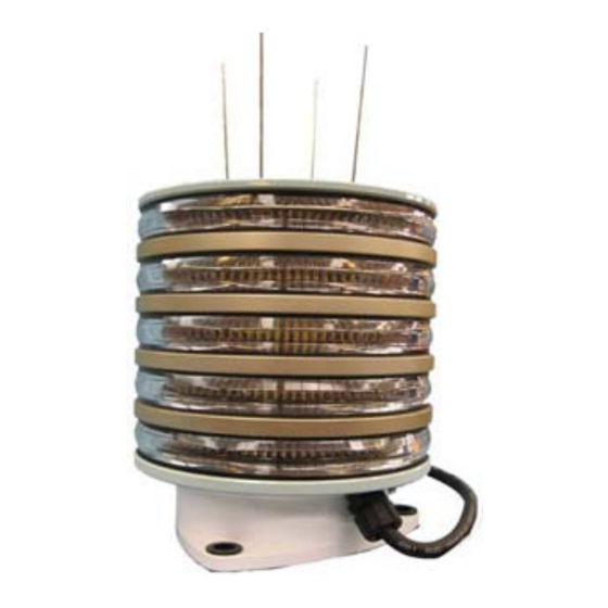
Vega VLB-44 5-Tier LED Lantern
Selection Criteria
Intensity selection should be based on the operational requirements of the aid. To determine the
intensity requirements for any aid, Districts shall use the standard procedures for selecting an
AtoN light signal as prescribed in the AtoN Technical Manual (Chapter 6, Section 6.B, page 6-1)
and the Visual Signal Design Manual (Chapter 3). These references describe how operational
1
Advertisement
Table of Contents

Summary of Contents for Vega Industries VLB-44
- Page 1 2.5 degree lantern to lighthouses or rock-solid structures unaffected by wind or waves. The VLB-44 is available with up to 8 tiers of LEDs to increase intensity. This lantern requires an external 12 VDC power source from a DC power supply or a legacy solar power system consisting of solar panels and rechargeable lead-acid batteries.
- Page 2 LED version 421. LEDs available in mid 2008 were designated version 422. The Solar Sizing Programs used to size a solar power system for VLB-44 have a picklist that is used to select the LED version. The picklist choices depend on the user-selected lantern and color.
- Page 3 Current pricing for Vega lanterns is available from your training team chief or COMDT (CG-432A) http://www.uscg.mil/hq/cg4/cg432/organization.asp. The following VLB-44 lanterns will be stocked at the SFLC in project 98A (free-issue) for approved buoy, fixed aid and lighthouse projects (contact Son Nguyen at above link.) VLB-44-10...
- Page 4 (Note: the codes for RCA remote needs to be verified. Use the Vega remote until positive confirmation is received.) You are now ready to program the Vega VLB-44 lantern. Gather the information needed to program the lantern; intensity and flash rhythm code (note: if the lantern is purchased directly from Vega for a specific project it may come pre-programmed.
- Page 5 DCB-224 in a lighthouse with a FL(2)W15 rhythm may have an existing flash rate of 0.1s FL, 4.9s EC, 0.1s FL, 9.9s EC (as detailed in the Light List). It is not practical to flash the VLB-44 at a 0.1 second rate. A typical rhythm would be 1s FL, 4s EC, 1s FL, 9s EC. Note that the period remains the same (15 seconds) and the duty cycle is 2s/15s x100=13.3% (close to the desired...
- Page 6 2 quick flashes, then display the flash rhythm for 16-20 seconds. • If the VLB-44 is the main light controlled by a SACII/III, the lantern must be commanded on both day and night, and intensity set for both day and night. The daylight control function is performed by the SACII/III and the lantern is controlled by power being applied at dusk and secured at dawn by the SACII/III.
- Page 7 A. Flash Rhythm. To start a programming session, gather the data for each operation. For example, the following VLB-44 has a flash rhythm of FL6(.6) and an intensity setting of 7280 candelas. The code for FL6(.6) is 337 and the intensity value is 7280. The remote is capable of many operations (more on that later).
- Page 8 (step 1). If the VLB-44 is the main light controlled by a SACII/III, the lantern must be commanded on both day and night, and intensity set for both day and night. The code to turn the lantern on during the day (ignoring the daylight control input) is 14109.
- Page 9 Vega VLB-44 Lantern 25 Jan 2011 - Rev 9 Programming – Reading a Program Setting The program settings can be deciphered by reading and recording (writing down) lantern flash sequences upon activation with the IR remote control. The flash rhythm and intensity are read as separate sequences and may be used to verify the setting(s) without reprogramming the lantern.
- Page 10 As an example, a fictitious light with a FL(2)W20 might have an existing rhythm of 0.1s FL, 4.9s EC, 0.1s FL, 14.9s EC. A suitable replacement using the VLB-44 would be a 1s FL, 4s EC, 1s FL, 14s EC. The mariner still sees 2 flashes every 20 seconds, the flash is longer providing a better bearing and the duty cycle is at the desired 10% (2/20x100=10%).
- Page 11 Vega VLB-44 Lantern 25 Jan 2011 - Rev 9 (cont’d) Custom Flash Rhythm The custom rhythm has been entered into the lantern’s memory. Now the lantern must be programmed to display that new rhythm. The code for a custom rhythm is 999.
- Page 12 **2.5 degree lantern is 10.9” Figure 1. For lighthouses requiring more than 8 tiers, the VLB-44 can be double-stacked (16 tiers) using the Mount-Kit-2 available directly from Vega. The kit is sandwiched between the lower lantern and leveling mount in the lighthouse with a tube passing through the lower lantern to the upper lantern.
- Page 13 Vega VLB-44 Lantern 25 Jan 2011 - Rev 9 Installation – VLB-44-10 on a Buoy Solar Panel Mounting Frame Note High Base For Buoys 1/2” Bolt Top of Radar Flat Washer Reflector Split Lock Washer Figure 2. Sandwich the panel stand between the lantern and buoy and attach with ½” threaded stainless steel bolts, flat washers, split lock washer and nuts, as shown in Figure 2.
- Page 14 Vega VLB-44 Lantern 25 Jan 2011 - Rev 9 Installation - VLB-44-10 on a Buoy (cont’d) hardware (no cross ribs, vertical reflectors, etc.). Drill four 9/32” diameter holes through the reflector. Install the junction box using the provided hardware. Route the wires through the stuffing tubes, as shown in Figure 4.
- Page 15 Vega VLB-44 Lantern 25 Jan 2011 - Rev 9 Installation – VLB-44-05 on a Structure (cont’d) Mount and level the lantern using three ½” stainless steel studs or bolts, as shown in Figure 5. Do not lose the plastic inserts in the base or over tighten the fasteners, crushing the inserts as they prevent galvanic corrosion.
- Page 16 Wiring is critical to ensure adequate voltage at the lantern. Lighthouses generally use multi- tiered lanterns and will use a significant amount of current. Expect the VLB-44 to use up to 1.25 amps per tier. Therefore, an 8 tier lantern will have a maximum current consumption of 10 amps.
- Page 17 Servicing Guide. Replace, if necessary using the procedure listed below. Power Cable Replacement The power cable for the VLB-44 is wired to the circuit board inside the lantern through a stuffing tube. Replacement cable should be 12/2 SOW, SOOW, SJOW, SJOOW for 3-8 tier lanterns and 16/2 for 1-2 tier lanterns (“S”...
- Page 18 Vega VLB-44 Lantern 25 Jan 2011 - Rev 9 Power Cable Replacement (cont’d) Black or Brown (+) White or Blue (-) Note how ends are sealed with heat shrink Green/Yellow (not used*) *Only used when double stacking 8 tier lanterns. For most applications a 2-wire power cable will suffice.
Need help?
Do you have a question about the VLB-44 and is the answer not in the manual?
Questions and answers