
Summary of Contents for Tyco Electronics TE3124
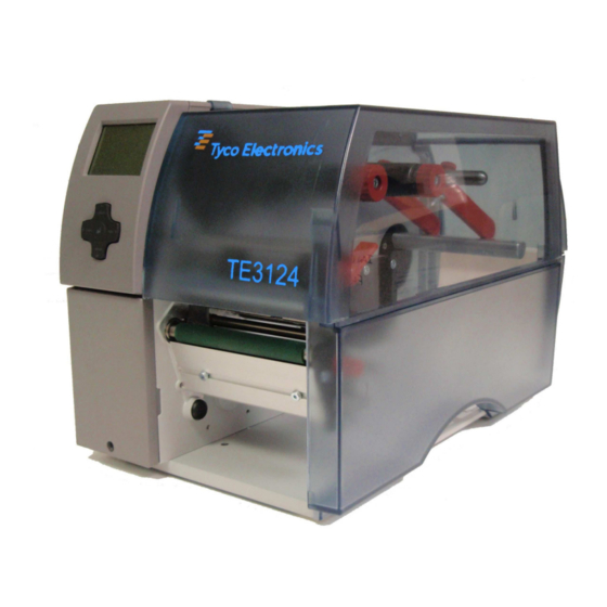
- Page 1 Identification Heat Shrink and Label Printer TE3124 (600dpi) Operator’s Manual EIL/MAN/031 Edition 1/08...
- Page 2 Operator's Manual EIL/MAN/031/ Rev 1 Copyright This documentation as well as translation hereof are property of Tyco Electronics UK Ltd. The replication, conversion, duplication or divulgement of the whole manual or parts of it for other intentions than its original intended purpose demand the previous written authorization by Tyco Electronics UK Ltd.
-
Page 3: Table Of Contents
Table of Contents Introduction ............................4 Instructions ............................... 4 Intended Use ............................4 Safety Instructions ............................ 4 Environment ............................. 5 Installation .............................. 6 Device Overview ............................6 Unpacking and Setting-up the Printer ...................... 8 Connecting the Device ..........................8 2.3.1 Connecting to the Power Supply ...................... -
Page 4: Introduction
• The device printer is intended exclusively for printing suitable materials that have been approved by the manufac- turer. Any other use or use going beyond this shall be regarded as improper use. Tyco Electronics shall not be liable for damage resulting from unauthorized use; the user shall bear the risk alone. •... -
Page 5: Environment
Introduction • Unauthorized interference with electronic modules or their software can cause malfunctions. • Other unauthorized work on or modifications to the device can also endanger operational safety. • Always have service work done in a qualified workshop, where the personnel have the technical knowledge and tools required to do the necessary work. • There are various warning stickers on the device. They draw your attention to dangers. Warning stickers must therefore not be removed, as then you and other people cannot be aware of dangers and may be injured. -
Page 6: Installation
Installation Device Overview 1 Cover 2 Guides 3 Roll retainer 4 Ribbon supply hub 5 Ribbon take-up hub 6 Print mechanics 7 Navigator pad 8 Display Fig. 1 Overview 9 Ribbon deflection roller 10 Printhead retainer with printhead 11 Print roller 12 Guides 13 Allen key 14 Printhead locking lever 15 Guide roller... - Page 7 Installation 19 Power switch 20 Power connection jack 21 Slot for PC Card Type II 22 Slot for CompactFlash memory card 23 Ethernet 10/100 Base-T 24 2 USB master ports for keyboard, scanner or service key 25 USB high-speed slave port 26 Serial RS-232 C port Fig.
-
Page 8: Unpacking And Setting-Up The Printer
Installation Unpacking and Setting-up the Printer Check label printer for damage which may have occurred during transport. Set up printer on a level surface. Remove foam transportation safeguards near the printhead. Check delivery for completeness. Contents of delivery: •... -
Page 9: Control Panel
Control Panel Structure of the Control Panel The user can control the operation of the printer with the control panel, for example: • Issuing, interrupting, continuing and canceling print jobs, • Setting printing parameters, e.g. heat level of the printhead, print speed, interface configuration, language and time of day, • Start the test functions, • Control stand-alone operation with a memory module, • Update the firmware. Many functions and settings can also be controlled by software applications or by direct programming with a computer using the printer’s own commands. -
Page 10: Printer States
Control Panel Printer States State Display Description Ready Ready The printer is in the ready state and can receive data. and configured symbol displays, such as time and date Printing label Printing label The printer is currently processing an active print job. and the number of the printed label in the print job. -
Page 11: Key Functions
Control Panel Key Functions The key functions depend on the current printer state: Active functions: Labels and symbols on the navigator pad keys light up. Active functions light up white in print mode (e. g. menu or feed). Active functions light up orange in the offline menu (arrows, key 8 ). Display State Function Ready... -
Page 12: Loading Material
Loading Material Notice! For adjustments and simple installation work, use the accompanying Allen key located in the upper section of the print unit. No other tools are required for the work described here. Loading Labels or Continuous Media from Roll 4.1.1 Positioning the Media Roll on the Roll Retainer Fig. -
Page 13: Inserting A Media Strip Into The Printhead
Loading Material Swivel the outer guide (3) upwards. Load label roll on the roll retainer in such a way that the labels can be inserted into the printhead in the right position. The printing side of the labels must be visible from above. Ensure approximately 4 cm of media protrudes out of the printhead. Push the roll until it makes contact with the inner guide (3). Swivel the outer guide (3) downwards onto the media hub (4). The roll must be braked slightly by the the guides when supplying media. -
Page 14: Loading Fanfold Labels
Loading Material Loading Fanfold Labels Fig. 8 Feed path of fanfold labels Turn lever (1) counterclockwise to lift the printhead. Loosen knurled screws (3), remove guides (4) from the axle (2) and re-mount the guides in such a way, that they reach below the roll retainer (5). Adjust the guides to the media width ( 4.1.1 on page 12). Position label stack (6) behind the printer. Ensure that the labels on the strip are visible from above. Push label strip between the guides (4) to print unit via the roll retainer (5). Insert label strip into printhead ( 4.1.2 on page 13). Set label sensor ( 4.1.3 on page 13). Turn lever (1) clockwise to lock the printhead. -
Page 15: Loading Transfer Ribbon
Loading Material Loading Transfer Ribbon Notice! With direct thermal printing, do not load a transfer ribbon; if one has already been loaded, remove it. Fig. 10 Transfer ribbon feed path Fig. 9 Load transfer ribbon Clean printhead before loading the transfer ribbon ( 6.3 on page 18). Turn lever (6) counterclockwise to lift the printhead. -
Page 16: Setting The Feed Path Of The Transfer Ribbon
Loading Material Setting the Feed Path of the Transfer Ribbon Transfer ribbon wrinkling can lead to print image errors. Transfer ribbon deflection can be adjusted so as to prevent wrinkles. Notice! The adjustment is best carried out during printing. Fig. 11 Setting the feed path of the transfer ribbon Read current setting on the scale (1) and record if necessary. Turn screw (2) with Allen key and observe the behavior of the ribbon. In the + direction, the inner edge of the ribbon is tightened, and the outer edge is tightened in the - direction. Setting the Head Locking System Fig. -
Page 17: Printing Operation
Printing Operation Attention! Printhead damage caused by improper handling! Do not touch the underside of the printhead with the fingers or sharp objects. Ensure that the labels are clean. Ensure that the label surfaces are smooth. Rough labels act like emery paper and reduce the service life ... -
Page 18: Cleaning
Cleaning Cleaning Information Danger! Risk of death via electric shock! Disconnect the printer from the power supply before performing any maintenance work. The label printer requires very little maintenance. It is important to clean the thermal printhead regularly. This guarantees a consistently good printed image and plays a major part in preventing premature wear of the printhead. -
Page 19: Fault Correction
Fault Correction Types of Errors The diagnostic system indicates on the screen if an error has occurred. The printer is set into one of the three possible error states according to the type of error. State Display Remark Correctable error pause flashes ... -
Page 20: Error Messages And Fault Correction
Fault Correction Error Messages and Fault Correction Error message Cause Remedy ADC malfunction Hardware error Switch the printer off and then on. If error recurs call service. Barcode error Invalid barcode content, e.g. alphanumeric Correct the barcode content. characters in a numerical barcode Barcode too big The barcode is too big for the allocated Reduce the size of the barcode or move it. - Page 21 Fault Correction Error message Cause Remedy No record found Refers to the optional memory card; Check programming and card contents. database access error No SMTP server The printer is configured for SMTP, but Switch off SMTP in the configuration. there is no SMTP server, or the SMTP Caution! Then a warning cannot be sent by server is not currently available.
-
Page 22: Media
Media Media Dimensions Labels Endless material Fig. 13 Label dimensions Dim. Designation Dim. in mm Label width 4 - 106 Label height 4 - 1000 Tear-off length > 30 Cut length with cutter CU4 > 2 with perforation cutter PCU4 >... -
Page 23: Device Dimensions
Media Device Dimensions Fig. 14 Device dimensions Dim. Designation Dim. in mm Distance printhead - cut edge with cutter CU4 18,8 with perforation cutter PCU4 19,5 Distance printhead - tear-off edge 13,5 Print width 105,6 Distance gap/reflective sensor - middle of paper track -53 - ±0 i.e. permissible distance of reflex or cut-out marks from the middle of the material Distance gap/reflective sensor - printhead 46,0 Table 9... -
Page 24: Reflex Mark Dimensions
Media Reflex Mark Dimensions Labels with reflex marks Endless material with reflex marks Fig. 15 Reflex mark dimensions Dim. Designation Dim. in mm Label distance > 2 Distance between print zones >2 Width of reflex mark > 5 Height of reflex mark 3 - 10 Distance mark - material edge -53 - ±0 Distance virtual label front edge - actual label front edge 0 up to A / recomm. -
Page 25: Cut-Out Mark Dimensions
Media Cut-out Mark Dimensions Labels with cut-out marks Endless material with cut-out marks for marginal cut-out marks minimum liner thickness 0,06 mm Fig. 16 Cut-out mark dimensions Dim. Designation Dim. in mm Label distance > 2 Distance between print zones >2 Width of cut-out mark >... -
Page 26: Licences
Licences Tyco Electronics Ltd Cheney Manor Industrial estate Swindon Wiltshire SN2 2QE EU Declaration of Conformity We declare herewith that as a result of the manner in which the machine designated below was designed, the type of construction and the machines which, as a result have been brought on to the general market comply with the relevant fundamental regulations of the EU Rules for Safety and Health. -
Page 27: Index
Index Adapting the roll retainer ....12 Label sensor setting .........13 Lithium battery ........5 Cleaning Loading fanfold labels.......14 printhead ........18 Loading labels ........12 print roller ........18 Loading labels from roll ....12 Cleaning information......18 Loading transfer ribbon.....15 Connecting .........8 Contents of delivery ......8 Control panel ........9 Media dimensions......22 Correctable error ......10...
Need help?
Do you have a question about the TE3124 and is the answer not in the manual?
Questions and answers