Table of Contents
Advertisement
D
E
S
MAXI-THERM
Glass Lined Indirect Water Heater
INSTALLATION AND OPERATING INSTRUCTIONS
I
G
N
E
Models:
MT040G
•
MT050G
•
MT079G
•
MT100G
•
Manufacturer of Hydronic Heating Products
P.O. Box 14818 3633 I. Street
Tel: (215) 535-8900 • Fax: (215) 535-9736 • www.crownboiler.com
D
T
O
Philadelphia, PA 19134
L
E
A
WARNING: Improper installa-
tion, adjustment, alteration,
service or maintenance can
cause property damage, injury,
or loss of life. For assistance or
additional information, consult a
qualified installer or service
agency. Read these instructions
carefully before installing or
using.
D
Advertisement
Table of Contents

Related Manuals for Crown Boiler MAXI-THERM MT040G


Summary of Contents for Crown Boiler MAXI-THERM MT040G
- Page 1 MAXI-THERM Glass Lined Indirect Water Heater INSTALLATION AND OPERATING INSTRUCTIONS Models: MT040G • MT050G • WARNING: Improper installa- tion, adjustment, alteration, MT079G • service or maintenance can MT100G • cause property damage, injury, or loss of life. For assistance or...
-
Page 2: Table Of Contents
CONTENTS Product Description................. 2 Specifications...................2 III. Designing A Maxi-Therm System............4 “Quick” Residential................5 Detailed Residential................6 Commercial..................9 Zone Design..................15 Before Starting Installation...............18 Locating the Maxi-Therm..............18 Piping....................20 Boiler Side..................20 Domestic Side..................24 VII. Wiring....................30 VIII. Start-up................... 34 Maintenance..................35 Operating Instructions..............36 Parts....................37 Appendix A: Whirlpool Sizing..............39... -
Page 3: Product Description
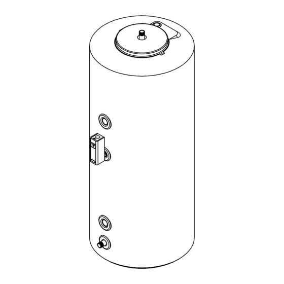
ASME requirements. Check with the local authority having jurisdiction before installing an MT079G or MT100G with a boiler having a total gross output in excess of 200,000 BTU/hr. II. SPECIFICATIONS Table 1: Specifications MAXI-THERM MT040G MT050G MT079G MT100G FIRST HOUR RATING (Gal/hr)* BOILER OUTPUT (BTU/hr) - Page 4 Figure 1a: MT040G and MT050G - General Configuration Figure 1b: MT079G and MT100G - General Configuration...
-
Page 5: Designing A Maxi-Therm System
THESE SIZING PROCEDURES ARE PROVIDED AS A GUIDE TO ASSIST THE PROFESSIONAL CON- TRACTOR IN SIZING MAXI-THERMS. BECAUSE OF THE LARGE VARIETY OF DEMAND SITUATIONS ENCOUNTERED IN THE FIELD, CROWN BOILER COMPANY CANNOT GUARANTEE THE SUITABIL- ITY OF THESE PROCEDURES TO ALL INSTALLATIONS. -
Page 6: Quick" Residential
(f). Table 2: Maxi-Therm “Quick Sizing” Table Clothes Description Occupants Baths Dishwasher Washer Maxi-Therm Boiler Output Small Office <10 ½-1* Yes * MT040G 30,000 Apartment 1-1 ½ MT040G 80,000 House 1-1 ½ MT040G 80,000 House 2-2 ½ MT050G 116,000... -
Page 7: Detailed Residential
METHOD B: “DETAILED” RESIDENTIAL 1) Record the total number of each type of fixture in column (c) of Worksheet 1. If a whirlpool (Jacuzzi) is installed, record all fixtures EXCEPT the whirlpool faucet. 2) For each line multiply the quantity entered in column (c ) by the corresponding hourly usage in column (b). - Page 8 WORKSHEET 1: SINGLE FAMILY RESIDENCE 135F WATER TOTAL 135F WATER PER FIXTURE PER FIXTURE NUMBER OF TYPE OF DESCRIPTION (Gal/hr) FIXTURES FIXTURE (Gal/hr) Shower: (3 GPM Head) 21.0 (5 GPM Head) 35.0 (7 GPM Head) 49.0 Bath (30 Gal. Tub) 21.0 Vanity Clothes Washer...
- Page 9 Figure 2: Completed Worksheet 1 and Boiler Output Graph From Example 1 WORKSHEET 1: SINGLE FAMILY RESIDENCE 135F WATER TOTAL 135F WATER PER FIXTURE PER FIXTURE NUMBER OF TYPE OF DESCRIPTION (Gal/hr) FIXTURES FIXTURE (Gal/hr) Shower: (3 GPM Head) 21.0 (5 GPM Head) 35.0 35.0...
-
Page 10: Commercial
METHOD C: COMMERCIAL 1) Table 3 shows demands for various fixtures found in commercial buildings in gallons per hour. To determine the hot requirements of the building: a) Using Worksheet 2, determine and record the total number of each type of fixture in the building under column (2). - Page 11 3) Several Maxi-Therms may be used together if needed. If this must be done keep the following in mind: • The first hour rating of several Maxi-Therms may be added together to give a first hour rating for the total system. •...
- Page 12 WORKSHEET 2: COMMERCIAL SIZING 135F WATER PER 135F WATER PER FIXTURE TOTAL NUMBER TYPE OF Fixture Description: (Gal/hr) OF FIXTURES FIXTURE (Gal/hr) Basins, Private Lavatory Basins, Public Lavatory Bathtubs Showers Circular Wash Sinks Semi Circular Wash Sinks Foot Basins Laundry, Stationary Tubs Kitchen Sink Dishwasher in Apartment Clothes Washer in Apartment...
- Page 13 Total Column (3) Possible Maximum Demand 1978 Demand Factor 0.25 Probable Maximum Demand 494.5 Hourly Dishwasher Requirement Hourly Laundry Requirement Adjusted Probable Maximum Demand 594.5 50000 100000 150000 BOIL ER OUT PUT (BT U/h r ) Figure 4a: MT040G Ratings at Different Boiler Outputs...
- Page 14 50000 100000 150000 BOILER OUTPUT (BTU/hr) Figure 4b: MT050G Ratings at Different Boiler Outputs 50000 100000 150000 200000 BOILER OUTPUT (BTU/hr) Figure 4c: MT079G Ratings at Different Boiler Outputs...
- Page 15 Figure 4d: MT100G Ratings at Different Boiler Outputs Table 4: 135F Water Available at Various Flow Rates Starting with a Fully Recovered Maxi-Therm Boiler Output Draw Rate (GPM) Model 12.0 15.0 (BTU/hr) MT040G Time (min.) 11.9 103149 Gallons. 35.6 33.9 31.2 29.2 MT050G Time (min.)
-
Page 16: Zone Design
Use Table 5 or a circulator manufacturer’s literature to select a circulator, which will develop the required flow rate at the pressure drop calculated. Example 3: Size a circulator for a zone with a MT040G and the following pipe and fittings: 10 ft 1”... - Page 17 WORKSHEET #3: Pressure Drop Calculations Through Maxi-Therm Zone Pressure Drop (ft head) Fitting Description Quantity 8 Gal/min 10 Gal/min Total MT040G Coil 2.60 MT050G Coil 2.60 MT079G Coil 4.40 MT100G Coil 5.70 1 ft 1" St. Pipe 0.05 0.08 1 ft 1-1/4" St. Pipe 0.02...
- Page 18 Figure 4: Example of Use of Worksheet 3 WORKSHEET #3: Pressure Drop Calculations Through M axi-Therm Zone Pres s ure Drop (ft head) Fitting Des cription Quantity 8 Gal/min 10 Gal/min Total MT040G Coil 2.60 2.60 MT050G Coil 2.60 MT079G Coil 4.40 MT100G Coil 5.70...
-
Page 19: Before Starting Installation
The anode rod is located in the hand hole cover on the MT040G and MT050G, so there is only a clearance requirement on the top of the Maxi-Therm. All clearances not shown in Figure 5 are 0”. - Page 20 Maxi-Therm zone. If long runs exist between the boiler and Maxi-Therm, it is advisable to insulate the piping. MODEL "X" "Y" MT040G MT050G MT079G MT100G * Additional clearance may be...
-
Page 21: Piping
VI. PIPING CAUTION Do not connect a Maxi-Therm to a boiler system having a significant amount of make up water or radiant tubing without an oxygen barrier. Doing so may cause premature failure of the Maxi-Therm coil. WARNING Install a relief valve on the boiler per the boiler manufacturer’s instructions. Also refer to the boiler manufacturer’s instructions and the authority having jurisdiction for other possible boiler-side piping requirements, such as low water cut-offs or flow switches. - Page 22 Figure 6: Boiler-Side Piping Using Circulator Zones Figure 7: Boiler-Side Piping Using Zone Valves (2-Way)
- Page 23 Therm. The boiler manifold piping must be sized so that each coil has the flow rate called for in Table 1. For example, if two MT040G’s are to be manifold together, the circulator and zone piping common to both tanks...
- Page 24 Figure 9: Boiler-Side Piping in a Low Temperature System Using a Heat Exchanger Figure 10: Boiler-Side Piping in a Low Temperature System Using a Mixing Valve...
-
Page 25: Domestic Side
Figure 11: Boiler-Side Piping for Multiple Maxi-Therms DOMESTIC SIDE PIPING BASIC DOMESTIC PIPING Figure 12 shows typical domestic water piping for a Maxi-Therm. All components except the thermostat are provided by the installer. The function of the components shown are as follows: a) Thermostat (required) - This control is provided by Crown and must be installed in the location indicated. - Page 26 If the Maxi-Therm is connected to a boiler with a Gross Output GREATER than the “Max. T&P Valve Capacity” shown below, install a T&P valve having a capacity greater than or equal to the “Max T&P Valve Capacity”. MODEL MAX. T&P VALVE CAPACITY MT040G 140400 MT050G 154200 MT079G...
-
Page 27: Vii. Wiring
MAXI-THERM PIPING WITH A “MIXING VALVE” Usually, the maximum temperature of the outlet water will stay near the setting of the Maxi-Therm thermostat. In some cases, however, hot water usage patterns can cause the outlet water temperature to rise significantly above the control setting. - Page 28 Figure 12: Basic Domestic-Side Piping Figure 13: Domestic-Side Piping Using a Mixing Valve...
- Page 29 Insulate dashed piping Figure 14a: Domestic-Side Piping Using a Recirculation Line (MT040G, MT050G) Insulate dashed piping Figure 14b: Domestic-Side Piping Using a Recirculation Line (MT079G, MT100G)
- Page 30 Figure 15: Domestic-Side Piping for Multiple Maxi-Therms...
-
Page 31: Wiring
The following general notes apply to all wiring: 1) Wiring must be done in accordance with all codes. In the absence of any codes, the system must be wired in accordance with the National Electric Code (ANSI/NFPA 70-latest edition). 2) The control system for the boiler, Maxi-Therm, and heating zones must be on a dedicated circuit. The current rating of this circuit will depend on the total number and size of loads in the system, however it should in no case be less than 15 AMPS. - Page 32 Figure 16: Non-Priority Circulator Zoning Using Honeywell R845a’s Figure 17: Priority Circulator Zoning...
- Page 33 ZONE VALVES (2-WAY PRIORITY) Figure 19 is a connections diagram for a priority zone system using Honeywell V8043F motorized valves. An R8285B relay is used which is equipped with its own transformer and a set of SPDT contacts. The Maxi-Therm control is connected to terminal R and G on the R8285B so that when the Maxi-Therm control calls for heat, the relay coil is energized.
- Page 34 Figure 19: Zone Valve Wiring (2-Way, Priority) Note: Connect Zone Valve Port “A” to Maxi-Therm, Port “B” to Heating Zone, “AB” to boiler return Figure 20: Zone Valve Wiring (3-Way, Priority Using Honeywell V8044E1101 )
-
Page 35: Start-Up
VIII. START-UP 1) Make sure that the system is free of leaks and that air is purged from the system. After completing all domestic water connections, flush the domestic side of the Maxi-Therm thoroughly before leaving the installation. Flushing the domestic water side of the Maxi-Therm will minimize the presence of WARNING Never attempt to fill a hot empty boiler. -
Page 36: Maintenance
For the anode rod to work properly it must be electrically bonded to the Maxi-Therm Tank. On the MT040G and MT050G, this is done with two ground wires that bond the anode rod to the clean-out cover and the clean-out cover to the tank. -
Page 37: Operating Instructions
X. OPERATING INSTRUCTIONS WARNING There are no user serviceable parts on this product. Attempts to service this product by someone other than a licensed plumber or heating technician could void the warranty, cause property damage, personal injury or loss of life. DANGER •... -
Page 38: Parts
Crown Boiler Co. 3633 I St. Philadelphia Pa. 19134 215-535-8900 Parts - MT040G, MT050G K E Y # P A R T D E S C R IP T IO N C R O W N P .N . Q T Y . - Page 39 Parts - MT079G, MT100G KEY # PART DESCRIPTION CROWN P.N. QTY. THERMOSTAT (L4006A2114) 35-3200 3/4 SHORT WELL 35-1010 CLEAN OUT COVER 220005 CLEAN OUT GASKET 220006 M12 x 30mm CAP SCREW 900020 ANODE ROD (MT079G) 220011 ANODE ROD (MT100G) 220012 JACKET WRAPPER (MT079G) 220079 JACKET WRAPPER (MT100G)
-
Page 40: Appendix A: Whirlpool Sizing
SOLUTION: Since the whirlpool tub has a volume (70 gal) greater than that of the MT040G (38.0 gal.), select an MT079G (79.3 gal) instead of the MT040G. The boiler output stays at 120,000 BTU/hr. The recovery time is: 44982 x 79.3 = 29.7 minutes... - Page 41 Manufacturer of Hydronic Heating Products P.O. Box 14818 3633 I. Street Philadelphia, PA 19134 Tel: (215) 535-8900 • Fax: (215) 535-9736 • www.crownboiler.com Rev 2 05/03...
Need help?
Do you have a question about the MAXI-THERM MT040G and is the answer not in the manual?
Questions and answers