Table of Contents
Advertisement
Advertisement
Table of Contents

Related Manuals for SlipStream 30 cc Super Chipmunk

Summary of Contents for SlipStream 30 cc Super Chipmunk
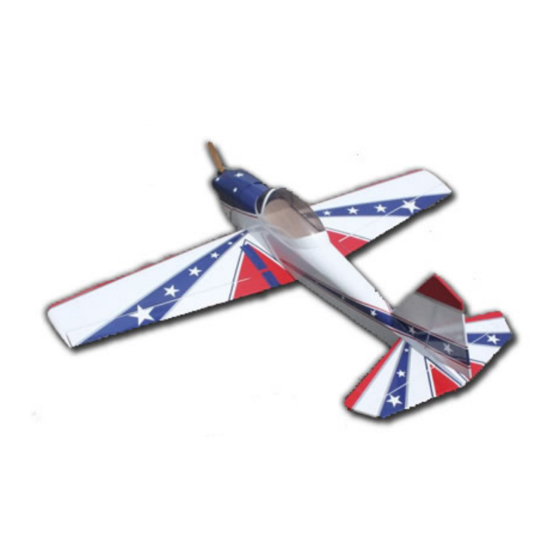
- Page 1 30 cc Super Chipmunk Assembly Manual Congratulations on your purchase this excellent almost-ready-to-fly model! This ARF adopts latest design features and emphasizes high performance light weight and fun. The plane designed professional engineers and built skilled craftsmen.
-
Page 2: Specifications
Specifications: Wing Span: 80” (2030mm) Length(Including Spinner): 69” (1750mm) Wing Area: 935 in² (60.4 dm²) Flying Weight: 11 to 13 lbs(5-5.5kg) Engine: .91-1.20(2C) 1.10-1.40 (4C) 20 - 35cc Gas Radio: 4+ Channels Servos : 6 servos required 80 oz/in FEATURES Latest Structure Light weight construction and high structural strength Super Quality... - Page 3 We have found this to be helpful with models intended for higher speed flight or models with unusually large hinge gaps. Slipstream aircraft utilize a very tight double beveled hinge line and do not normally require this step. Sealing the hinge gaps is therefore...
- Page 4 FUSELAGE, STABILIZERS AND TAIL WHEEL ASSEMBLY: NOTE: Please review this section carefully as you are required to mount the tail wheel at the same time. 1. Start by prepping the fuselage. Locate the hole for the tail gear at the bottom rear of the fuselage and use the soldering iron carefully to make a nice clean opening if necessary.
- Page 5 3. Cut the covering away where the horizontal stabilizer will seat as shown below. 4. Locate the horizontal stabilizer and slide it in the slot as shown in the picture below. 5. Use a ruler (or any of your favorite method) to check for square-ness. Once satisfied, mark the top and bottom of the horizontal stabilizer to cut away the covering as shown in the pictures below.
- Page 6 6. Carefully cutaway the covering where the glue will be applied. See pictures below.
- Page 7 7. Prepare some 30 minutes epoxy and apply it to the exposed section of the stabilizer and install it onto the fuselage. Carefully check the alignment of the stabilizer. Once satisfied, wipe off the excess epoxy with a paper towel soaked in rubbing alcohol. 8.
- Page 8 10. Install the tail wheel through the bottom of the fuselage. See picture below. 11. Locate the vertical stabilizer and rudder. Mount the vertical stabilizer onto the fuselage. Trial fit the rudder onto the vertical stabilizer and mark the spot where the tail wheel rod will be bent.
- Page 9 13. Prepare the rudder by cutting a slot to recess the tail gear wire. Also drill a hole the size of the tail gear wire. Harden the cut and drilled area with thin CA. 14. Prepare the vertical stabilizer for gluing onto the fuselage. Cut off the covering as shown below.
- Page 10 16. Locate the vertical stabilizer extension and prepare the fuselage for installation. Remove the covering as shown in the pictures below. Glue it on with either medium CA or epoxy. 17. Locate the rudder and hinges and prepare it for installation. Use a little epoxy in the hole where the tail wheel tiller will reside to strengthen it.
- Page 11 18. Locate the elevators and the hinges to glue in the elevators onto the horizontal stabilizers. Glue it in using the same method as was used in the rudder installation above. 19. Locate the control horns for the elevators and prepare for installation. See pictures below for the locations for the control horn.
- Page 12 20. Locate the rudder control horn assembly. See pictures below for installation of the control horns. Ensure that the rudder cables running through the slots do not rub the fuselage.
- Page 13 ENGINE INSTALLATION 1. Look at the firewall and you will see the lightly scribed centerline marked for the center of your engine mount. You can darken it with a pen for visibility. 2. Mark the location of mounting bolts (Here, a DLE 30 is used). Drill out the mounting holes for your mounting hardware.
- Page 14 3. The distance of the firewall to the back plate of the spinner is about 7-31/4”. The standoff length required will be 3-1/8”, which will give about a 1/8” clearance between the back plate and the cowl. See pictures below for mounting the engine. 4.
- Page 15 5. Now prepare to mark the cowl for installation. You will want to mount the engine and use a 3” spinner back plate for use as a guide. Make some paper strip and tape them to the fuselage as shown below. Drill a hole that will be big enough to accept a 4-40 screw (or you can use the wood screw provided which the author does not recommend).
- Page 16 7. Cut out appropriate openings in the cowl for engine and muffler. Also make cuts in the bottom of the cowl for cooling purposes.
- Page 17 CANOPY INSTALL 1. Locate the canopy and align it on the fuselage as shown below. You will need canopy glue for this step. Once you are satisfied with the alignment, apply the canopy glue. Tape down the canopy with making tape so that it won’t move while it is curing.
- Page 18 2. Use a hot soldering iron and carefully remove the covering where the servo wire will come out of. Also use the soldering iron to remove the covering for the wing bolts. 3. Mix some 30 minute epoxy and apply it on the wing joiner and exposed ribs and glue the two wing halves together.
- Page 19 4. Locate the wing bolt reinforcement plate. Remove the covering where the wing bolts will come through. Use the wing bolts and align it onto the bottom of the wings and mark the area where the covering needs to be removed. Mix some epoxy and glue down the wing bolt plate.
- Page 20 6. Locate the control horns and install them as shown in the pictures below. You can use the same method as was used in the installation of the horns for the elevator. 7. Route the extensions lead out as shown below. There is a guide thread pre-installed in the wings to help thread the servo wires.
- Page 21 9. Locate the landing gear and securing hardware as shown below. 10. Install the gear as shown below. Harden the screw holes with CA. 11. Locate the wheel-pants, wheels, and the wheel collars.
- Page 22 12. Install the wheel pants, wheel collars and wheels in the order shown in the pictures below. 13. Prior to securing everything down, make a flat spot on the gear where the collars reside so that they won’t slip.
- Page 23 14. Reinstall the wheel pants, wheel and collars and secure everything. Locate the mounting hardware to secure the wheel pants and install it as shown below. FUEL TANK INSTALLTION: 1. Locate the tank mounting tray and the fuel tank. Mount the tank onto the tank tray as shown below.
- Page 24 The above picture also shows the equipment install. This could vary based on individual setup. BALANCING AND PRE-FLIGHT: The Chipmunk will balance right on the main wing spar. It is a very easy flying airplane and fly and land very much like a trainer. FINAL ASSEMBLY AND PRE-FLIGHT INSPECTI0NS: 1.
Need help?
Do you have a question about the 30 cc Super Chipmunk and is the answer not in the manual?
Questions and answers
que dual rate y exponenciales recomienda el fabricante