Table of Contents
Advertisement
Quick Links
Advertisement
Chapters
Table of Contents

Related Manuals for Meggitt 60-2

Summary of Contents for Meggitt 60-2
- Page 1 System 60-2 Autopilot Pilot's Operating Handbook...
- Page 2 SYS 60-2 POH * Asterisk indicates pages changed, added, or deleted by List of Effective Pages revision. Retain this record in front of handbook. Upon receipt of a Record of Revisions revision, insert changes and complete table below. Revision Number...
- Page 3 SYS 60-2 POH Page Intentionally Blank 2nd Ed: Nov 01, 01...
-
Page 4: Table Of Contents
SYS 60-2 POH Table of Contents Section Page Introduction......................1-3 Block Diagram....................2-3 Autopilot Overview....................3-3 System 60-2 Programmer/Annunciator..........3-3 Roll Modes of Operation...............3-4 3.2.1 Heading (HDG)................3-4 3.2.2 Navigation (NAV)..............3-4 3.2.3 Reverse (REV).................3-5 Pitch Modes of Operation..............3-5 3.3.1 Vertical Speed (VS)..............3-5 3.3.2 Altitude (ALT)................3-6 3.3.3... - Page 5 SYS 60-2 POH Table of Contents Section Page 4.2.2 Pitch Axis Modes..............4-20 4.2.2.1 Vertical Speed (VS)..........4-20 4.2.2.2 Altitude Hold (ALT)..........4-21 4.2.2.3 Intercepting and Coupling the Glideslpoe..4-21 4.2.2.4 Manual Arm/Automatic Capture......4-22 4.2.2.5 Elevator Trim Indicator..........4-25 4.2.2.6 Optional Autotrim............4-26 Flight Director Operations (Optional)..........4-26 4.3.1...
- Page 6 SYS 60-2 POH List of Figures Figure Page System 60-2 Block Diagram................2-3 System 60-2 Programmer/Annunciator............3-3 Directional Gyro....................4-6 VOR/LOC/GPS.....................4-8 Straight-In Localizer Approach and Tracking (DG)........4-10 Procedure Turn Localizer Approach and Tracking (DG)......4-11 Back Course Straight-In Approach (DG)............4-12 Back Course Procedure Turn (DG)..............4-13 Horizontal Situation Indicator (HSI)...............4-14...
- Page 7 SYS 60-2 POH Page Intentionally Blank 2nd Ed: Nov 01, 01...
-
Page 8: Introduction
SYS 60-2 POH SECTION 1 INTRODUCTION 2nd Ed: Nov 01, 01... - Page 9 SYS 60-2 POH Page Intentionally Blank 2nd Ed: Nov 01, 01...
- Page 10 SYS 60-2 POH Introduction The primary purpose of the System 60-2 Pilot Operating Handbook (POH) is to provide pilots with step-by-step Functional Preflight and In-Flight Op- erating Procedures for the installed system. Notice This manual should be used in conjunction with an FAA approved autopilot Airplane Flight Manual Supplement (AFMS), Pilots Operating Handbook Supplement (POHS) or Supplemental Flight Manual (SFM).
- Page 11 SYS 60-2 POH Page Intentionally Blank 2nd Ed: Nov 01, 01...
-
Page 12: Block Diagram
SYS 60-2 POH SECTION 2 BLOCK DIAGRAM 2nd Ed: Nov 01, 01... - Page 13 SYS 60-2 POH Page Intentionally Blank 2nd Ed: Nov 01, 01...
- Page 14 (O PT IO N A L) YAW S E R VO YAW D A M PE R (O PT IO N A L) (O PT IO N A L) Fig. 2-1. System 60-2 Block Diagram 2nd Ed: Nov 01, 01...
- Page 15 SYS 60-2 POH Page Intentionally Blank 2nd Ed: Nov 01, 01...
-
Page 16: Autopilot Overview
SYS 60-2 POH SECTION 3 AUTOPILOT OVERVIEW 2nd Ed: Nov 01, 01... - Page 17 SYS 60-2 POH Page Intentionally Blank 2nd Ed: Nov 01, 01...
-
Page 18: System 60-2 Programmer/Annunciator
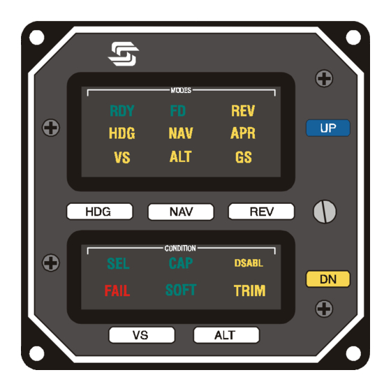
System 60-2 Programmer/Annunciator Fig. 3-1. System 60-2 Programmer/Annunciator The System 60-2 Programmer/Annunciator is a rate based autopilot that controls the roll and pitch axis of the aircraft. The autopilot's main func- tion is to convert pilot commands to logic signals for both the roll and pitch computers. -
Page 19: Roll Modes Of Operation
SYS 60-2 POH Roll Modes of Operation 3.2.1 Heading (HDG) The HDG mode provides heading preselect and turns through the use of the heading bug on the Directional Gyro (DG) or optional Horizontal Situation Indicator (HSI). 3.2.2 Navigation (NAV) The NAV mode provides roll commands for automatic intercept and track- ing of selected VOR/LOC/RNAV/LORAN/GPS navigational signals. -
Page 20: Reverse (Rev)
SYS 60-2 POH 3.2.3 Reverse (REV) REV mode provides roll commands for automatic intercept and tracking of the back course localizer inbound or the front course localizer out- bound. Pitch Modes of Operation NOTE: Before engaging a pitch mode of operation, a roll mode must first be engaged. -
Page 21: Altitude (Alt)
SYS 60-2 POH 3.3.2 Altitude (ALT) The ALT mode engages the altitude hold mode, capturing the altitude attained at the time of activation. 3.3.3 When the VS mode is activated, the UP modifier switch will increase the rate-of-climb or decrease the rate-of-descent at 160 FPM for each sec- ond of continuous switch depression. - Page 22 SYS 60-2 POH NOTE: For aircraft without auto trim, or where auto trim is disabled or turned off, the UP/DN switches are used to annunciate out of trim conditions when either the VS or ALT modes are engaged. If up trim is required, the UP switch will illuminate.
- Page 23 SYS 60-2 POH Page Intentionally Blank 2nd Ed: Nov 01, 01...
-
Page 24: Procedures
SYS 60-2 POH SECTION 4 PROCEDURES 2nd Ed: Nov 01, 01... - Page 25 SYS 60-2 POH Page Intentionally Blank 2nd Ed: Nov 01, 01...
-
Page 26: Pre-Flight Procedures
SYS 60-2 POH Procedures Pre-Flight Procedures NOTE: To perform the system function check, adequate DC voltage must be supplied to the system, either 12 or 24 VDC, depending on the aircraft. 4.1.1 Roll Axis The following is a step by step procedure for preflighting the Roll Axis: 1. -
Page 27: Pitch/Altitude And Vertical Speed
SYS 60-2 POH 4.1.2 Pitch/Altitude and Vertical Speed The following is a step by step procedure for pre-flighting the Pitch/ Altitude and Vertical Speed Systems: 1. Be sure the Autopilot Master Switch is ON, and that a roll axis mode has been selected. -
Page 28: Autotrim
SYS 60-2 POH 5. If the autopilot is equipped with optional autotrim, proceed with the following steps: A. Place Trim and Autopilot Master Switches to ON. B. Operate Manual Trim Switch (both segments) nose DN. Autopilot TRIM annunciator flashes and trim moves nose down (check manual trim wheel). -
Page 29: Normal Operating Procedures
SYS 60-2 POH NORMAL OPERATING PROCEDURES NOTE: In order to activate any mode of the System 60-2 Autopilot, the Master Switch must be in the ON position and the RDY annunciator must be illuminated. 4.2.1 Roll Axis Modes 4.2.1.1 Heading 1. - Page 30 SYS 60-2 POH NOTE: If the VOR needle is at full-scale deviation, the autopilot will establish a 45º intercept angle to the desired course. As the aircraft approaches the selected radial, the autopilot senses the closure rate, and gradually, smoothly shallows the intercept angle. The point at which this turn begins is variable, depending on the aircraft position and closure rate to the radial.
-
Page 31: Vor Approach (Dg)
SYS 60-2 POH Approximately 45 seconds later, the maximum turn rate is reduced to 15% of standard rate (Soft Gain), and the lowest level of sensitivity is achieved, identified by the NAV and SOFT annunciation's. The CAP annunciation extinguishes. This condition provides low activity levels during station passage when VOR signals are erratic. -
Page 32: Localizer Intercept And Tracking (Dg)
SYS 60-2 POH During a VOR approach, it is recommended that the NAV mode switch be depressed just after TO/FROM reversal after the needle has stabilized at the Final Approach Fix inbound. This returns the system to capture dynamics and reinstates the high sensitivity gain scheduling. - Page 34 Procedure Turn Localizer Approach and Tracking (DG) a. Tune navigation radio to LOC frequency. b. Set heading bug to published outbound LOC heading. c. Push REV mode switch. a. Set heading bug to outbound procedure turn heading. b. Press HDG mode switch. In 90 increments, set heading bug to inbound procedure turn heading.
- Page 36 Back Course Procedure Turn (DG) Back Course a. Tune navigation receiver to LOC frequency. b. Set heading bug to published inbound front course heading. c. Press NAV mode switch. a. Set heading bug to outbound procedure turn heading. b. Press HDG mode switch. In 90 increments, set heading bug to inbound procedure turn heading.
- Page 37 SYS 60-2 POH 4.2.1.5 VOR/Localizer Intercept and Track (HSI Option) Fig. 4-7. Horizontal Situation Indicator If your aircraft is equipped with an optional HSI, the autopilot will receive both VOR left/right information and course information. With an HSI, the heading bug is not used during radio tracking. To make a VOR or Localizer approach, tune the navigation receiver to the required frequency.
-
Page 38: Dual Mode Intercept
SYS 60-2 POH 4.2.1.6 Dual Mode Intercept NOTE: During operations with an HSI, simultaneous activation of both the HDG and NAV modes will provide selected angle intercepts. In flying a radial or localizer intercept, the autopilot will follow the heading bug until the aircraft reaches the proper on course turn point. - Page 40 Procedure Turn Localizer Approach and Tracking (Optional HSI) a. Tune navigation radio to LOC frequency. b. Set published inbound LOC course heading with course pointer. c. Push REV mode switch. a. Set heading bug to published outbound procedure turn heading. b.
-
Page 43: Pitch Axis Modes
SYS 60-2 POH 4.2.2 Pitch Axis Modes NOTE: A Roll Mode must be selected before selecting a Pitch Mode. 4.2.2.1 Vertical Speed (VS) When establishing an automatic climb out to a desired altitude (without optional ALT Selector Alerter), press and release the VS mode switch to engage the vertical speed mode. -
Page 44: Altitude Hold (Alt)
SYS 60-2 POH 4.2.2.2 Altitude Hold (ALT) Upon reaching the desired or assigned altitude, press and release the ALT switch. The altitude hold mode will engage at the altitude reached at the time of engagement. There is typically no need to "lead" the desired altitude. -
Page 45: Manual Arm/Automatic Capture
SYS 60-2 POH NOTE: GS arming will occur when the above conditions have existed for 10 seconds. Illumination of the GS annunciator will occur, indicating arming has been accomplished. The ALT annunciator remains on. GS capture is indicated by extinguishing of the ALT annunciation at GS intercept. -
Page 48: Elevator Trim Indicator
SYS 60-2 POH NOTE: To fly a holding pattern, if inbound to the outer marker while in NAV mode, press the NAV switch a second time to disable the GS arming. When the outer marker is reached, press and release the HDG switch, and rotate the heading bug in the direction of the turn. -
Page 49: Optional Autotrim
SYS 60-2 POH 4.2.2.6 Optional Autotrim If the autopilot is equipped with optional Autotrim, the aircraft elevator trim will be maintained automatically when the Trim Master Switch is ON and a pitch mode is activated. When the Trim Master Switch is ON, the trim annunciators are disabled. -
Page 50: Two Cue
SYS 60-2 POH 4.3.2 Two Cue This system, also known as an Attitude Director Indicator (ADI), is automatically activated when the autopilot is engaged. Activation is indicated by illumination of the FD annunciator. This system contains a vertical steering bar for roll commands, and a horizontal steering bar for pitch commands. - Page 51 SYS 60-2 POH Page Intentionally Blank 4-28 2nd Ed: Nov 01, 01...
-
Page 52: Appendixes
SYS 60-2 POH SECTION 5 APPENDIXES 2nd Ed: Nov 01, 01... - Page 53 SYS 60-2 POH Table of Contents Appendix A: System Failure and Caution Annunciations..5-3 Roll Axis..........5-3 Pitch Axis........5-4 Appendix B: Specifications..........5-5 2nd Ed: Nov 01, 01...
-
Page 54: Appendix A: System Failure And Caution Annunciations
SYS 60-2 POH Appendix A System Failure and Caution Annunciations Roll Axis ANNUNCIATION CONDITION ACTION Flashing RDY for 5 Indicates autopilot seconds. disconnect. All annunciations except RDY are cleared. Flashing RDY, then Turn coordinator gyro Check instrument extinguish. rotor speed low. Auto power;... -
Page 55: Pitch Axis
SYS 60-2 POH Appendix A System Failure and Caution Annunciations Pitch Axis ANNUNCIATION CONDITIONS ACTION Flashing GS Indicates off Check attitude and glideslope centerline power. Add or by 50% or more. reduce power as appropriate. Flashing GS with Indicates nonvalid... -
Page 56: Appendix B: Specifications
SYS 60-2 POH Appendix B Specifications Programmer Power required 14/28 VDC Weight 1.9 lbs Dimensions 3.3 x 3.3 x 5.2 in. Turn Coordinator Power required 14/28 VDC Flag voltage detector operating limits 9 VDC (Approx.) Flag RPM detector operating limits... - Page 57 SYS 60-2 POH Appendix B Specifications (Cont'd) Roll Servo Power required 14/28 VDC Current Included in system value power required. Weight 2.9 lbs. Dimensions 7.25 x 3.75 in. Pitch Servo/Trim Sensor Power required 14/28 VDC Current Included in system value power required.
-
Page 58: Glossary
SYS 60-2 POH SECTION 6 GLOSSARY 2nd Ed: Nov 01, 01... - Page 59 SYS 60-2 POH Page Intentionally Blank 2nd Ed: Nov 01, 01...
- Page 60 SYS 60-2 POH GLOSSARY Term Meaning AFMS Airplane Flight Manual Supplement Altitude Approach Autopilot Air Traffic Control Capture Course Deviation Indicator Direct Current Directional Gyro Down DSBL Disable Federal Aviation Administration Flight Director Feet Per Minute Global Positioning System Glideslope...
- Page 61 SYS 60-2 POH Page Intentionally Blank 2nd Ed: Nov 01, 01...
- Page 62 S-TEC Corporation A Meggitt Aerospace Systems Company One S-TEC Way · Municipal Airport Mineral Wells, Texas 76067-9236 USA Telephone 940/325-9406; FAX 940/325-3904 1-800-USA-STEC www.s-tec.com Information in this document is subject to change without notice. ©2001 S-TEC Corporation. All rights reserved. Printed in the United States of America.
Need help?
Do you have a question about the 60-2 and is the answer not in the manual?
Questions and answers