
Summary of Contents for Cyber Controller
- Page 1 Cyber Controller INSTRUCTION MANUAL Please read this manual thoroughly before use and keep it handy for future reference.
-
Page 2: Warnings And Cautions
WARNINGS and CAUTIONS WARNINGS TO REDUCE THE RISK OF FIRE OR ELECTRIC SHOCK. - DO NOT EXPOSE THIS PRODUCT TO RAIN OR MOISTURE. - DO NOT INSERT ANY MEALMETALLIC OBJECTS THROUGH THE VENTILATION GRILLS OR OTHERS OPENINGS ON THE EQUIPMENT. CAUTIONS EXPLANATION OF GRAPHICAL SYMBOLS The lighting flash with arrowhead symbol, within a triangle, is intended to alert the user... -
Page 3: Compliance Statement
COMPLIANCE STATEMENT FCC INFORMATION : THIS EQUIPMENT HAS BEEN TESTED AND FOUND TO COMPLY WITH THE LIMITS FOR A CLASS A DIGITAL DEVICE, PURSUANT TO PART 15 OF THE FCC RULES. THESE LIMITS ARE DESIGNED TO PROVIDE REASONABLE PROTECTION AGAINST HARMFUL INTERFERENCE WHEN THE EQUIPMENT IS OPERATED IN A COMMERCIAL ENVIRONMENT. -
Page 4: Important Safeguards
Using the appliance under such conditions may result in fire, electric shock or serious damage. If the controller body gets dirty, turn the power off and wipe the surface with a soft cloth. - Do not use chemical agents such as alcohol or benzene. -
Page 5: Table Of Contents
1. INTRODUCTION 2. PACKAGE CONTENTS 3. INSTALLATION CONFIGURATION 3.1 Basic Configuration of DVR & Cyber Controller 3.2 Basic Configuration of Matrix System & Cyber Controller 3.3 The Example of Multi Configuration 4. OPERATING CONTROLS 4.1 Front View 4.2 Rear View 4.3 Operation by Part... -
Page 6: Introduction
1. INTRODUCTION The Cyber Controller, Cyber Scan Dome, Video Matrix System & Digital Video Recorder make up the building blocks for any surveillance/security system. Using a multiple Cyber Controller and multiple dome cameras, no place is too large for monitoring and recording. Extendable and flexible architecture facilitates remote control functions for a variety of external switching devices such as DVR, Matrix System and Cyber Scan Dome Camera. -
Page 7: Package Contents
* Please use the unit in the range of a guarantee temperature and humidity of operation. * Please set ID of a camera as the same number as the input channel to DVR. 2. PACKAGE CONTENTS The Cyber Controller contains the following. ① Cyber Controller Unit ------- 1 ② Junction Box ------- 1 ③... -
Page 8: Installation Configuration
3. INSTALLATION & CONFIGURATION 3.1 Basic Configuration of DVR & Cyber Controller Junction Box... -
Page 9: Basic Configuration Of Matrix System & Cyber Controller
3. INSTALLATION & CONFIGURATION 3.2 Basic Configuration of Matrix System & Cyber Controller Junction Box... -
Page 10: The Example Of Multi Configuration
3. INSTALLATION & CONFIGURATION 3.3 The Example of Multi Configuration... -
Page 11: Operating Controls
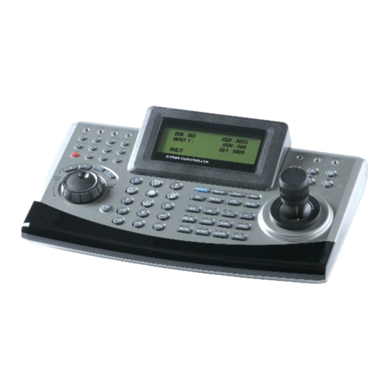
4. OPERATING CONTROLS 4.1 Front View ① LED Indicator ⑨ PTZ Keypad ② DVR Keypad ⑩ Joy Stick ③ DVR Playback ⑪ Controller Keypad ④ Jog Shuttle ⑫ SHIFT Button ⑤ CTRL Button ⑬ Zoom/Focus/IRIS ⑥ Numeric Button ⑭ 4 Line LCD ⑦... -
Page 12: Rear View
Notice : A Modem cable not supplied so make certain you have the correct cable when you connect to the Cyber controller. ② ID DIP Switch : It is used to select Cyber controller ID. ③ RJ-45 JACK (IN/OUT) IN : Data Input port from the slave controller. -
Page 13: Operation By Part
4. OPERATING CONTROLS 4.3 Operation by Part LEDs Part CAM : The Camera status indication. DVR : The DVR status Indication. MON : The Monitor(Matrix switcher) status Indication. TX/RX : Communication status indication. POWER : Turned on while the power is supplied. SHIFT : Turned on when SHIFT button is pressed. - Page 14 MON : It is used to select the Monitor No. Controller Function Part SHIFT : Combination button for another function SETUP : It is used to setup the Controller’s configurations. LOCK : It is used to lock all Controller functions. Matrix Function Part CH : It is used to select the channel.
- Page 15 4. OPERATING CONTROLS PTZ Camera Function Part PRESET : It is used to set the Preset function. TOUR : It is used to set the Tour function. PTRN : It is used to set the Pattern function. SCAN : It is used to set the Auto Scan function. MENU : It is used to select the Set up Menu.
-
Page 16: Operation
5. OPERATION 5.1 Power Turn on the controller power after all domes have initialized (wait at least 30 seconds) 1. Input 12VDC 1A to the Cyber controller & junction box 2. Connect Cyber controller and the junction box by RJ-45 Cable. -
Page 17: System Setup
Go to previous menu. ENT button Save & Exit 5.3 SYSTEM SETUP Press SETUP button to setup the system of the controller. Below screen shows the controller setup menu. 1. SYSTEM INFO * Push the joystick to the up/down and 2. -
Page 18: Password Setup
5. OPERATION 5.3.2 PASSWORD SETUP When you want to change the password, you can change the password in password setup menu. The unit requires the initial password before operation. The factory default password is 8888. CURRENT PASSWORD ① Input the current password and Press ENT button. INPUT? : NEW PASSWORD ②... -
Page 19: Back Light Time
Note : Be careful to select this mode since you can not INITIALIZE ALL DATA? revert the current data forever. 1: YES 2: NO 5.3.5 SYSTEM RESET DO YOU WANT TO The controller restarts the system. But all saved data is not RESTART THE SYSTEM? initialized. 1: YES 2: NO... -
Page 20: Camera Setup
○ Input the Camera ID number and Press ENT → CAM ID:[001 – 001] → CAM ID:[999 -– 999] Push the joystick right. COMM.:CYBER SCAN I COMM.:CYBER SCAN I BAUD :9600 BPS BAUD :9600 BPS PORT :RS-485 PORT :RS-485 COMMUNICATION PROTOCOL Setting: In the Camera ID Range, You should choose the ○... - Page 21 Baud Rate, push the joystick left/right or twist the joy stick clockwise/counterclockwise. If you set the controller to RS-232, controller sends the data through the RS-232 port. If you choose RS- 485/422, it sends the Communication protocol through the OUT port.
-
Page 22: Dvr Setup
5. OPERATION 5.3.7 DVR SETUP Set up DVR ID Range, the Protocol , Baud Rate of the DVR, and Output Port. You can select Individual Setup or Whole Setup. Navigate the Cursor by pushing the joy stick up or down. Cursor moves to the desired position. DVR ID Setting : You can select the DVR ID which you want to set from DVR ID to DVR ID. - Page 23 Baud Rate, push the joystick left/right or twist the joy stick clockwise/counterclockwise. If you set the controller to RS-232, controller sends the protocol through the RS-232 port. If you choose RS-485/422, it sends the Communication protocol through the OUT port.
-
Page 24: Lock
5. OPERATION 5.4 LOCK If you don’t want another person (not authorized) to manipulate the controller, you can lock the Cyber controller by pressing LOCK button. 5.4.1 Lock Setting Input the current password and Press ENT DVR:001 CAM:0001 LOCK SETTING? :... -
Page 25: Dimension
6. DIMENSION A. Cyber Controller B. Junction Box... -
Page 26: Specification
3X Axis Joy Stick Built In Pan/Tilt Pan : Left/Right, Tilt : Up/Down Key Features Zoom In/Out, Focus Near/Far, IRIS Open/Close, DVR / Matrix /Cyber Scan Dome control, Slave Controller Extendable Multi-Protocol Cyber Scan (I,II) / P-D / P-P Connection... -
Page 27: Appendix A - The List Of Glb(Short) Key
APPENDIX B - The List of GLB(Short) Key If you use Cyber Scan dome camera and Cyber controller, you can use the following GLB short cut key for the easy operations without accessing the main menu of the dome unit. (Cyber Scan protocol only) Note : Press GLB button, after press the numeric button. - Page 28 APPENDIX B - The List of GLB(Short) Key Area Title On/Off Toggle Operation Title On/Off Toggle Flag Display On/Off Toggle Time Display On/Off Toggle 3. Dome Operations Functions Flip Mirror/Reverse Flip...
-
Page 29: Appendix B - Trouble Shooting
Please check the wiring connection between the controller and the junction box. If the controller is not a. Please check the main power and power working consumption of the controller unit. b. Please check if the controller is in the lock mode. -
Page 30: Appendix C-Optional Item
APPENDIX C-OPTIONAL ITEM A. Cyber Scan Dome Camera B. Cyber Scan Pre-Pack Dome Camera C. Digital Video Recorder D. Video Matrix System... - Page 31 MEMO...
Need help?
Do you have a question about the Controller and is the answer not in the manual?
Questions and answers