Advertisement
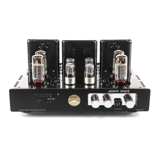
GALAXY 34 VACUUM TUBE STEREO INTEGRATED/POWER AMPLIFIER
Thank you for using AUDIO SPACE Galaxy Series vacuum tube stereo integrated
/power amplifier. Please read this instruction manual carefully before unpacking the
contents and using your amplifier.
SPECIFICATIONS
n Input impedance
n Output impedance
n Output power
n Damping factor
n Frequency response
n T.H.D.
n Total gain
n Input sensitivity
n S/N ratio
n Channel balance
n Channel separation
n Vacuum tubes
n Power requirement
n Dimension
n Weight
* Information and diagrams in this instruction are subject to change without notice.
WARNING
DO NOT OPEN THE CHASSIS OF THIS PRODUCT
To reduce the risk of electric shock, do not remove the bottom cover of amplifier.
Do not attempt to repair the product yourself.
No user serviceable parts inside. Refer all service to qualified service personnel.
Keep liquids away from the amplifier. If liquid is spilled into the unit, disconnect
the AC power cord from the unit at once and consult your authorized dealer.
>89k ohm (RCA/Direct In)
4, 8 ohm
16W×2 (TRIODE-CLASS AB PUSH-PULL)
32W×2 (ULTRALINEAR-CLASS AB PUSH-PULL)
>5
20Hz∼30kHz -1dB
<1% 20Hz∼20kHz (REF. OUTPUT)
25dB
300mV∼600mV
>80dB (HUM NOISE<3mV)
<1dB 20Hz∼20kHz (MAX. VOLUME)
>60dB (1kHz∼3.3kHz)
V1, V2, V3, V4: EL34×4
V5, V6: 6N8P (6SN7) ×2
V7, V8: 6N9P (6SL7) ×2
AC∼230V±5% 50/60Hz
330×400×190mm (D×W×H)
22.5kg (N.W.) / 26.2kg (G.W.)
1
Advertisement
Table of Contents

Related Manuals for Audio Space GALAXY 34


Summary of Contents for Audio Space GALAXY 34
- Page 1 GALAXY 34 VACUUM TUBE STEREO INTEGRATED/POWER AMPLIFIER Thank you for using AUDIO SPACE Galaxy Series vacuum tube stereo integrated /power amplifier. Please read this instruction manual carefully before unpacking the contents and using your amplifier. SPECIFICATIONS n Input impedance >89k ohm (RCA/Direct In) n...
-
Page 2: Important Safety Information
Any possible adjustment inside the chassis or service required should to be referred to authorized Audio Space Acoustic Laboratory Ltd. dealer or other qualified electronics technician. - Page 3 • If the power cord must pass near a heater, make sure the cord is far enough from the heater so as to prevent power cord from melting from direct heat or come into contact with the heater accidentally. • If the power cord is damaged, replace it before operating the unit again. 6.
-
Page 4: Audio Input
(II) UNPACKING Besides this instruction manual, you will find the following contents: (1) one AUDIO SPACE Galaxy 34 amplifier, (2) a power supply cord, (3) handling gloves and wiping clothe, (4) two pieces of spare fuse, (5) a remote-control unit (batteries supplied). - Page 5 • POWER Plug the power cord into the power socket on the rear panel and the other end of the cord into an electrical outlet. (IV) POWERING ON When you are sure the connections are correct, turn on the “POWER” switch on the front panel of this amplifier.
-
Page 6: Troubleshooting
pre-marked 0.3V point on the lower scale of the meter as shown in the diagram below. Repeat the above procedure for each of the output tubes (V1 to V4). Alternatively, a voltmeter can be used to measure the bias voltage if higher accuracy is desired. - Page 7 circuits...
- Page 8 DIAGRAMS DIAGRAM 1 - FRONT PANEL MUTE INPUT SEL. AUX1 AUX2 TR/UL SEL. DIRECT IN TR/UL INDICATOR REMOTE METER VOLUME METER SEL. HEADPHONE JACK POWER SWITCH DIAGRAM 2 - REAR PANEL CD INPUT AUX1 INPUT AUX2 INPUT DIRECT INPUT REC. OUT L.CH SPEAKER OUTPUT R.CH SPEAKER OUTPUT POWER INPUT SOCKET...
- Page 9 DIAGRAM 3 - REMOTE CONTROL UNIT MUTE VOLUME INPUT SELECTOR TRI/UL SELECTOR DIAGRAM 4 - VACUUM TUBE INSTALLING POWER TRANSFORMER AUDIO TRANSFORMER BIAS ADJ. & BIAS TEST TERMINALS * REMARK: V1, V2, V3, V4: EL34 V5, V6: 6N8P V7, V8: 6N9P...
- Page 10 DIAGRAM 5 - CONNECTIONS...
Need help?
Do you have a question about the GALAXY 34 and is the answer not in the manual?
Questions and answers