Table of Contents
Advertisement
Advertisement
Table of Contents

Related Manuals for Akiyama Pulsar


Summary of Contents for Akiyama Pulsar
- Page 1 User Manual...
-
Page 2: Table Of Contents
1.3. Rear panel ......................................5 1.4. Connections ...................................... 6 2. SOFTWARE INSTALATION AND SETUP ............................... 7 2.1. PULSAR Akiyama ASIO Drivers ............................... 7 2.1.1. Akiyama ASIO drivers’ installation ............................7 2.1.2. Akiyama ASIO drivers Configuration ............................8 2.2. Traktor 2 ......................................8 2.2.1. - Page 3 PULSAR. User Manual Intended to alert the user to the presence of important operation maintenance (servicing) instructions literature accompanying this appliance. The lightning flash with arrowhead symbol within the equilateral triangle is intended to alert the use to the presence of un-insulated “dangerous voltage”...
- Page 4 Safe this manual at reach so you can go back to the basic in case you need it. PRELIMINARY Check the contents of the PULSAR box and find the following items: 1- Controller 1- Installation and instructions CD...
-
Page 5: Controls And Connections
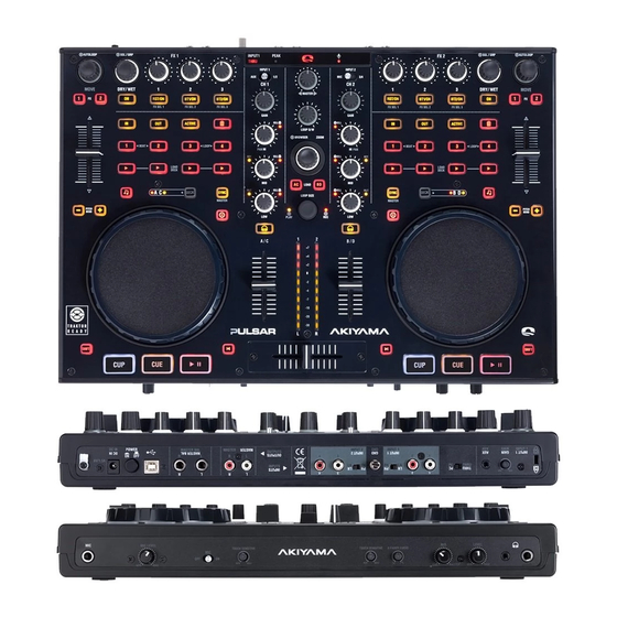
PULSAR. User Manual 1. CONTROLS AND CONNECTIONS 1.1. Top Panel 1. Controls distribution for an optimal use of Virtual DJ and 5. Dual FX units control with 4 knobs and 4 buttons for each Traktor 2. unit. 2. Control of up to 4 Decks. MIDI notes are sent through 6. -
Page 6: Rear Panel
PULSAR. User Manual wheel. Setting the sensitivity too low may not engage the touch will allow you to hear more of the Cue level. Turning the knob even while pressing firmly on the wheel. to the MASTER position (right) will allow you to hear more of 5. -
Page 7: Connections
PULSAR. User Manual 1.4. Connections 1. Before making or changing connections, switch off the 4. Connect the RCA pin cords to the inputs on your amplifier. power and disconnect the power cord from the AC outlet. CAUTION: Be sure to use the supplied control cord. Using 2. -
Page 8: Software Instalation And Setup
PULSAR. User Manual 2. SOFTWARE INSTALATION AND SETUP Before you can start using Akiyama PULSAR it is necessary to install Akiyama ASIO drivers to optimize the performance of the sound card of PULSAR. Also you will need DJ Software. We will explain how to install Traktor 2 LE and how to configure Traktor 2 LE as well as Traktor 2 PRO. -
Page 9: Akiyama Asio Drivers Configuration
Traktor Setup Wizard in this manual. 2.2. Traktor 2 PULSAR is bundled with Traktor 2 LE. We will go through the steps to install and configure Traktor 2 LE and PRO to be controlled by PULSAR. -
Page 10: Mac Installation
PULSAR. User Manual Select the folder where setup will install files and click “Next”. Traktor 2 will be successfully installed. Click “Finish” to exit from the Installation Wizard. 2.2.2. MAC Installation Execute the Traktor 2 installation file. Installation will start with the verification of the setup package. - Page 11 PULSAR. User Manual Select “Agree” and continue with installation wizard. Type you password and select “Install Software”. Following will appear a window showing the Installation Type Wait until the following window appears: information. Press “Continue”. Traktor 2 will be successfully installed. Click “Close” to exit Select the folder where setup will install files and click “Install”.
-
Page 12: Traktor 2 Le Registration
Start Guide … in the Service Center. Wizard” and the Welcome window will pop up. Connect PULSAR to your computer and click “Next”. Type your e-mail and Password if you already own a user account. Otherwise you must create a new User Account. - Page 13 PULSAR. User Manual Choose “Akiyama” as manufacturer and “Pulsar LE” or “Pulsar” Here, you have to select the desired deck layout. on model depending on if you are using Traktor 2 LE or PRO. NOTE: You must configure the controller accordingly (For Again confirm this selection with “Next”...
-
Page 14: Functions And Controls
PULSAR. User Manual 3. FUNCTIONS AND CONTROLS Traktor 2 LE mapping is compatible with the default mode in 3.1. Stand-alone controls which MIDI messages are sent through channels 1 to 4. For users using Traktor PRO, make sure that the Deck Layout Selection step is configured correctly. -
Page 15: Traktor 2 Le
PULSAR. User Manual 3.3. Traktor 2 LE - 3: Turn the control to adjust the FILTER parameter. 1. AUTOLOOP - BT2/ON: FILTER parameter On/Off. - FX1 & FX2: No function. - AUTOLOOP: Turn the control to select loop size. Press the control to set the loop. - Page 16 PULSAR. User Manual - SCRATCH ( ): Scratch mode On/Off. If Scratch mode is off 9. SHIFT. you can use the jog to modify the pitch bend. - JOG WHEEL: Turn the jog wheel to scratch or modify the The Shift button provides a second MIDI layer for the pitch bend.
-
Page 17: Traktor 2 Pro
PULSAR. User Manual 3.4. Traktor 2 PRO - DRY/WET (SGL & GRP): This parameter controls the mix TRACK DECK between the original direct signal (Dry; full left position) and the processed effect signal (Wet; full right position). 1. AUTOLOOP Shift (SGL): Turn the control to select the effect desired. - Page 18 PULSAR. User Manual - BT2/ON (SGL): Parameter On/Off. This parameter depends Shift (Loop Set): These buttons let you set loops of on the selected effect. established size. Available sizes in order are 1, 4, 8 and 16 - BT2/ON (GRP): 3rd effect of the unit On/Off.
- Page 19 PULSAR. User Manual SAMPLE DECK. Shift (Copy from Loop Rec.): Set the Loop Recorder loop on slot 2. These functions will be available if the controller is configured - ACTIVE: Set sample size to original value. in Mode 2.
-
Page 20: Setup And Firmware Update
PULSAR. User Manual 4. SETUP AND FIRMWARE UPDATE There are two approaches to set the device. One is setting Current Firmware Version through the Settings and Update software. The other is directly control by the hardware. Before you update firmware for this device you had better recheck the firmware version. -
Page 21: Channel Settings
PULSAR. User Manual Following functions you can set the device by your 4.3.3. Sample buttons setting requirements. You can change the Samples setting by holding the left deck 4.3.1. Channel settings “DECK SWITCH” button for 3 seconds and press the “Channel 2 monitor Cue”... -
Page 22: Apendix
8H 8 24 40 56 72 88 104 120 136 152 168 184 200 216 232 248 you can see at the table PULSAR MIDI MAP. We can send the 9H 9 25 41 57 73 89 105 121 137 153 169 185 201 217 233 249... - Page 23 PULSAR. User Manual PULSAR MIDI MAP BUTTON MIDI COMMAND MIDI COMMAND SHIFT+ KEY & KNOB LEFT and RIGHT DECK AUTO_LOOP 09,9n,01,7F 09,9n,01,00 0x33 AUTO_LOOP(knob) 0B,Bn,01,41(Increment) 0B,Bn,01,3F(Decrement) 0x1F FX_ON1 09,9n,02,7F 09,9n,02,00 0x34 FX_ON2 09,9n,03,7F 09,9n,03,00 0x35 PITCH_FADER 0E,En,00,00 0E,En,7F,7F 09,9n,04,7F...
- Page 24 PULSAR. User Manual PULSAR MIDI MAP LEDs LED ON LED OFF LEDS LEFT and RIGHT DECK FX_ON1 09,9n,02,7F 09,9n,02,00 FX_ON2 09,9n,03,7F 09,9n,03,00 09,9n,04,7F 09,9n,04,00 09,9n,05,7F 09,9n,05,00 LOOP_ACTIVE 09,9n,06,7F 09,9n,06,00 DELETE 09,9n,07,7F 09,9n,07,00 HOT_CUE1 09,9n,08,7F 09,9n,08,00 HOT_CUE2 09,9n,09,7F 09,9n,09,00 HOT_CUE3...
- Page 25 PULSAR. User Manual PULSAR MIDI MAP BUTTON MIDI COMMAND MIDI COMMAND SHIFT+ MASTER_METER_R1 0B,Bx,04,0C 0B,Bx,04,00 MASTER_METER_R2 0B,Bx,04,18 0B,Bx,04,00 MASTER_METER_R3 0B,Bx,04,24 0B,Bx,04,00 MASTER_METER_R4 0B,Bx,04,30 0B,Bx,04,00 MASTER_METER_R5 0B,Bx,04,3C 0B,Bx,04,00 MASTER_METER_R6 0B,Bx,04,48 0B,Bx,04,00 MASTER_METER_R7 0B,Bx,04,54 0B,Bx,04,00 MASTER_METER_R8 0B,Bx,04,60 0B,Bx,04,00 MASTER_METER_R9 0B,Bx,04,6C 0B,Bx,04,00...
-
Page 26: Technical Specifications
PULSAR. User Manual 5.2. Technical specifications 1. GENERAL SECTION POWER SOURCE USB 5V 500mA DC6V, 2.0A DIMENSIONS 410mm (W) X 297mm (D) X 65 mm (H) WEIGHT 2.9kg 2. INPUT/OUTPUT IMPEDANCE & SENSITIVITY: (MAXIMUM GAIN, LOAD=100K) 2-1.INPUT IMPEDANCE AND REFERENCE INPUT LEVEL:... - Page 27 MORE THAN +6dB(2V) 6. USB Slave Player Section: (Signal Format: MP3, 128Kbps, SONY Sound Forge8.0) *1 (SONY Sound audio device type: Akiyama ASIO Driver default playback device: PULSAR 1/2 Windows Level at MAX.OUT) *2 (SONY Sound audio device type: Akiyama ASIO Driver default playback device :PULSAR 3/4 Windows Level at MAX.OUT)
- Page 28 C/ Praga, nº 11. Pol. Cova Solera 08191. Rubí - Barcelona (Spain) www.akiyamadj.com info@akiyamadj.com ...
Need help?
Do you have a question about the Pulsar and is the answer not in the manual?
Questions and answers