Lennox G61MPV?36B?045 Installation Instructions Manual
G61mpv series units
Hide thumbs
Also See for G61MPV?36B?045:
- Brochure & specs (4 pages) ,
- Service manual (105 pages) ,
- Installation instructions manual (67 pages)
Table of Contents
Advertisement
E 2011 Lennox Industries Inc.
Dallas, Texas, USA
THIS MANUAL MUST BE LEFT WITH THE
HOMEOWNER FOR FUTURE REFERENCE
Do not store or use gasoline or other
flammable vapors and liquids in the
vicinity of this or any other ap-
pliance.
Installation and service must be
performed by a qualified installer,
service agency or the gas supplier.
01/11
*2P0111*
INSTALLATION
INSTRUCTIONS
G61MPV SERIES UNITS
GAS UNITS
506506−01
01/2011
Supersedes 07/2010
Table of Contents
WARNING
FIRE OR EXPLOSION HAZARD.
Failure to follow safety warnings exact-
ly could result in serious injury, death,
or property damage.
WHAT TO DO IF YOU SMELL GAS:
D Do not try to light any appliance.
D Do not touch any electrical switch; do not
use any phone in your building.
D Leave the building immediately.
D Immediately call your gas supplier from a
neighbor's phone. Follow the gas supplier's
instructions.
D If you cannot reach your gas supplier, call
the fire department.
Page 1
. . . . . . . . . . . . . . . . . . . . . . . . . . . . . . .
. . . . . . . . . . . . . . . . . . . . .
. . . . . . . . . . . . . . . . . . . . . . .
. . . . . . . . . . . . . . . . . . . . . . . . . . . . . .
. . . . . . . . . . . . . . . . . . . . . . . . . . . . . . . . . . . . . . .
. . . . . . . . . . . . . . . . . . . . . . . . . . . . . . . . . . . . . . . .
. . . . . . . . . . . . . . . . . . . . . . . . . . . . . . . . . .
. . . . . . . . . . . . . . . . . . .
. . . . . . . . . . . . . . . . . . . . . . . . .
. . . . . . . . . . . . . . . . . . . . .
. . . . . . . . . . . . . . . . . . . . . . . . . . . . . .
. . . . . . . . . . . . . . . . . . . . . . . . . . . . . . . . . . .
. . . . . . . . . . . . . . . . . . . . . . . . . . . . . . . . . . . . .
. . . . . . . . . . . . . . . . . . . . . . .
. . . . . . . . . . . . . . . . . . . . . . . . . . . . . . . . . .
. . . . . . . . . . . . . . . . . . . . . .
. . . . . . . . . . . . . . . . . . . . . . .
. . . . . . . . . . . . . . . . . . . . . . . .
. . . . . . . . . . . . . . . . . . . . . . . . . . . . . . . . . . . . . .
. . . . . . . . . . . . . . . . . . . . . . . . . . . . . . .
. . . . . . . . . . . . . . . . . . . . . . . . . . . . . .
. . . . . . . . . . . . . . . . . . . .
*P506506-01*
Litho U.S.A.
2
3
4
4
. . . . . . . . . . .
5
6
. . . . . . . . . . . . .
6
. . . . . . . . . . . . . . . . . .
9
15
16
16
19
20
21
36
38
45
55
56
57
59
60
. . . . . . . . .
63
64
69
70
. . . . . . . . . . . . . .
71
506506−01
Advertisement
Table of Contents
Troubleshooting

Related Manuals for Lennox G61MPV?36B?045


Summary of Contents for Lennox G61MPV?36B?045
-
Page 1: Table Of Contents
INSTALLATION INSTRUCTIONS E 2011 Lennox Industries Inc. Dallas, Texas, USA G61MPV SERIES UNITS GAS UNITS 506506−01 01/2011 Supersedes 07/2010 Litho U.S.A. Table of Contents Unit Dimensions ....... -
Page 2: Unit Dimensions
G61MPV Unit Dimensions − inches (mm) *60C and 60D size units installed in upflow applications that require air volumes over 1800 cfm (850 L/s) must have one of the following: 1. Single side return air with transition, to accommodate SUPPLY AIR 20 x 25 x 1 in. -
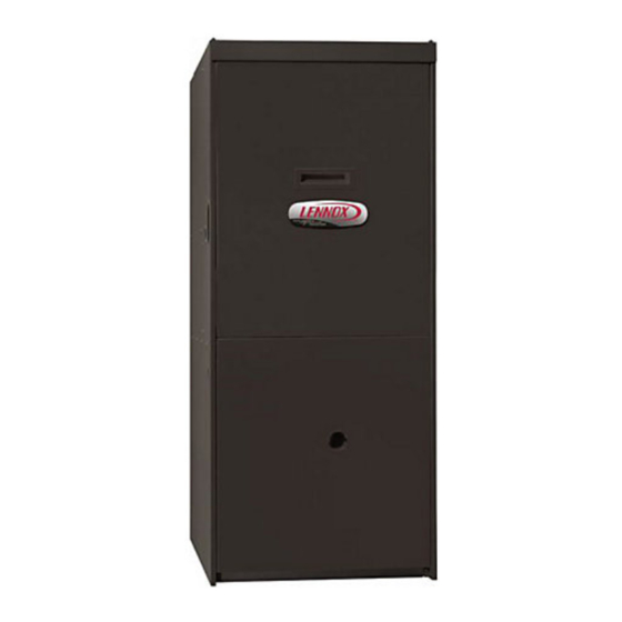
Page 3: G61Mpv Parts Arrangement
G61MPV Parts Arrangement TOP CAP DuralokPlus HEAT EXCHANGER ASSEMBLY CABINET BURNER BOX ASSEMBLY GAS VALVE AND MANIFOLD *G61MPV−36B−045 units are equipped with two switches. FLUE COLLAR COMBUSTION AIR PRESSURE WARM HEADER PROVE SWITCHES* (COLLECTOR) COMBUSTION AIR INDUCER CONDENSER COIL BURNER PRIMARY LIMIT ACCESS PANEL... -
Page 4: Shipping And Packing List
This control NOTE − G61MPV−60C−110 and G61MPV−60C−111 units ensures compatibility with Lennox’ Harmony III zone con- also include a 2" diameter PVC street elbow, which is trol system, as well as a thermostat which provides humid- shipped on the blower deck in the heating compartment. -
Page 5: Use Of Furnace As Construction Heater
Use of Furnace as Construction Heater NOTE − Furnace must be adjusted to obtain a temperature Lennox does not recommend the use of G61MPV units as rise within the range specified on the unit nameplate. Failure a construction heater during any phase of construction. -
Page 6: General
All furnace operating conditions (including ignition, in- supervisor. put rate, temperature rise and venting) must be verified Lennox Industries Inc. according to these installation instructions. P.O. Box 799900 Dallas, TX 75379−9900 General Combustion, Dilution &... - Page 7 air that could be used for combustion out of the house. separated by a door. Though an area may appear to be un- Unless outside air is brought into the house for combus- confined, it might be necessary to bring in outdoor air for tion, negative pressure (outside pressure is greater than combustion if the structure does not provide enough air by inside pressure) will build to the point that a downdraft...
- Page 8 Air from Outside When ducts are used, they shall be of the same cross−sec- tional area as the free area of the openings to which they If air from outside is brought in for combustion and ventila- connect. The minimum dimension of rectangular air ducts tion, the confined space shall be provided with two perma- shall be no less than 3 inches (75 mm).
-
Page 9: Installation − Setting Equipment
NOTE − G61MPV−36B and −36C units with 1/2 hp blower Installation − Setting Equipment motors are equipped with three flexible legs and one rigid leg. The rigid leg is equipped with a shipping bolt and a flat WARNING white plastic washer (rather than the rubber mounting Do not install the furnace on its front or its back. - Page 10 an airtight seal between the bottom of the furnace and the WARNING platform to ensure that the furnace operates properly and safely. The furnace is equipped with a removable bottom Improper installation of the furnace can result in per- panel to facilitate installation. sonal injury or death.
- Page 11 Removing the Bottom Panel Screw Bottom Cap Bottom Panel FIGURE 10 Optional Return Air Base (Upflow Applications Only −− For use with B, C and D cabinets only) 23 (584) Overall (102) Minimum (Maximum) 11 (279) (356) 22−7−16 Maximum Unit side return air (570) 14 (356) AIR FLOW...
- Page 12 Setting an Upflow Unit Refer to figure 13 for clearances in downflow applica- tions. When the side return air inlets are used in an upflow ap- plication, it may be necessary to install leveling bolts on the Downflow Application Installation Clearances bottom of the furnace.
- Page 13 Installation on Combustible Flooring Installation on Cooling Coil Cabinet 1 − Refer to reverse−flow coil installation instructions for 1 − When unit is installed on a combustible floor, an addi- correctly sized opening in floor and installation of cabi- tive base must be installed between the furnace and net.
- Page 14 (ordered separately, other necessary clearances. See figure 17. Lennox part number 56J18). Position the support frame on top of the blocks and install the unit on the 2 − Provide service platform in front of unit.
-
Page 15: Filters
4 − Set unit in drain pan as shown in figure 19. Leave 5−1/2 4 − Use #10−16 x 1/2 inch sheet metal screws to secure inches for service clearance below unit for condensate duct/grille cabinet to unit, taking care not to damage in- trap. -
Page 16: Duct System
versely affects the joint strength or chemical resistance of Duct System the cement. The cement shall show no gelation, stratifica- Use industry-approved standards to size and install the tion, or separation that cannot be removed by stirring. Re- supply and return air duct system. This will result in a quiet fer to the table 4 below for approved piping and fitting and low-static system that has uniform air distribution. - Page 17 Table 5 lists the available exhaust termination kits, as well as vent pipe equivalencies which must be used when siz- ing vent pipe. All Lennox vent terminations are PVC. Page 17...
- Page 18 TABLE 5 OUTDOOR TERMINATION KITS AND CORRESPONDING EQUIVALENCIES Vent Pipe Length Equivalency (feet) Outdoor Outdoor Exhaust Exhaust 1−1/2" 2" 3" 2" Wall Accelera- Acceler- 2" Wall 3" Wall Flush Mount Concentric Concentric Concen- Ring ator Plate Kit Plate Kit Termination VENT tric Kit (Dia.
-
Page 19: Vent Piping Guidelines
Contact Lennox’ Application Department for assis- it exits the termination. Refer to table 8. tance in sizing vent pipe in these applications. -
Page 20: Joint Cementing Procedure
NOTE − The flue collar on all models is sized to accommo- TABLE 7 MAXIMUM VENT PIPE LENGTHS date 2" Schedule 40 flue pipe. When vent pipe which is larger than 2" must be used in an upflow application, a 2" MAXIMUM EQUIVALENT VENT LENGTH FEET elbow must be applied at the flue collar in order to proper-... -
Page 21: Venting Practices
5 − Uniformly apply a liberal coat of PVC primer for PVC or 4 − Isolate piping at the point where it exits the outside wall use a clean dry cloth for ABS to clean inside socket or roof in order to prevent transmission of vibration to surface of fitting and male end of pipe to depth of fitting the structure. - Page 22 TYPICAL EXHAUST PIPE CONNECTIONS AND CONDENSATE TRAP INSTALLATION IN UPFLOW OR DOWNFLOW DIRECT OR NON−DIRECT VENT APPLICATIONS (Right−Hand Exit in Upflow Application Shown) 45° 45° 2−1/2", 3", OR 4" 2" PLUG PLUG TRANSITION G61MPV−070, 2" −071, −090, −091 2" with 2−1/2", 3", or VENT PLUG 2"...
- Page 23 TYPICAL AIR INTAKE PIPE CONNECTIONS UPFLOW OR DOWNFLOW DIRECT VENT APPLICATIONS 2−1/2", (Right−Hand Exit in Upflow Application Shown) 3" OR 2−1/2", 3" OR TRANSITION TRANSITION *2" PLUG (Must be −36B−045 glued in −36B−070 place) −36B−071 −36B−045 −36B−045 −36C−090 −36B−070 −36B−070 −60C−090 −36B−071 −36C−071...
- Page 24 TYPICAL AIR INTAKE PIPE CONNECTIONS DOWNFLOW NON−DIRECT VENT APPLICATIONS (Right−Hand Exit in Downflow Applications Shown) 2" SWEEP INTAKE DEBRIS SCREEN (Provided) 6 in. Max. PLUG PLUG (Must be glued in (Must be place) glued in place) 2" 18 in. 2" SWEEP ELL INTAKE DEBRIS SCREEN (Provided)
- Page 25 Canada for details. prevent freeze−ups. Heating cable installation kit is avail- Position termination according to location given in figure 29 able from Lennox. See Condensate Piping section for part or 30. In addition, position termination so it is free from any numbers.
-
Page 26: Vent Termination Clearances
‡ Permitted only if veranda, porch, deck or balcony is fully open on a minimum of two sides beneath the floor. Lennox recommends avoiding this location if possible. FIGURE 29 Page 26... - Page 27 ‡ Permitted only if veranda, porch, deck or balcony is fully open on a minimum of two sides beneath the floor. Lennox recommends avoiding this location if possible. FIGURE 30 Page 27...
- Page 28 Details of Intake and Exhaust Piping Terminations for FIELD SUPPLIED WALL TERMINATION OR Direct Vent Installation (15F74) WALL RING TERMINATION KIT NOTE − In Direct Vent installations, combustion air is tak- en from outdoors and flue gases are discharged to out- NOTE −...
- Page 29 TABLE 8 FIELD SUPPLIED WALL TERMINATION OR EXHAUST PIPE TERMINATION SIZE REDUCTION (15F74) WALL RING TERMINATION KIT G61MPV Termination With INTAKE ELBOW Exhaust Pipe Size MODEL Pipe Size 1−1/2" (38mm) 045, 070, 071 2" (51mm), 2−1/2" (64mm), NOTE − FIELD PROVIDED 090, 091 2"...
- Page 30 Intake Front View of Intake and Exhaust Exhaust Intake Exhaust TABLE 9 2" (51mm) 3" (76mm) Vent Pipe Vent Pipe A− Clearance above grade or average snow 12" (508MM) Min. 12" (508MM) Min. accumulation B−Horizontal 6" (152MM) Min. 6" (152MM) Min. separation between 24"...
- Page 31 1 1/2" (38mm) accelerator EXHAUST VENT Front View provided on 71M80 & 44W92 kits for SIZE G61MPV−36B−045, TERMINATION 36B−070 & 36B−071 PIPE PER INTAKE TABLE 8. 12” (305mm) FLASHING INTAKE (Not Furnished) Minimum Above Average Snow Accumulation Top View 1/2" (13mm) Foam Insulation in Unconditioned Space SHEET METAL STRAP (Clamp and sheet metal strap...
- Page 32 WALL TERMINATION KITS (CLOSE−COUPLE) EXTENDED VENT FOR GRADE CLEARANCE 2 inch (51 mm) 22G44 (US) 3 inch (76 mm) 44J40 (US) If Intake and Exhaust Pipe is less than 12 in. (305 mm) above snow accumulation or other obstructions, FIELD−PROVIDED field fabricated piping must be installed.
- Page 33 G61MP DIRECT VENT APPLICATION SIZE TERMINATION STRAIGHT−CUT OR USING EXISTING CHIMNEY ANGLE−CUT IN DIRECTION PIPE PER TABLE 8. OF ROOF SLOPE * 12" (305mm) ABOVE AVE. SNOW 1/2" (13mm) FOAM 3" − 8" EXHAUST VENT ACCUMULATION (76mm− INSULATION 8" − 12" 1/2"...
- Page 34 12" (305mm) MAX. for 2" (51mm) CONDENSATE TRAP LOCATIONS 20" (508mm) MAX. for 3" (76mm) UNCONDITIONED (Unit shown in upflow position) SPACE Horizontal Horizontal 6" (152mm) SIZE TER- left and right and MINATION optional optional *WALL SUPPORT PIPE PER downflow downflow TABLE 8.
- Page 35 SCREW cable kit may be used on the condensate trap and line. Heating cable kit is available from Lennox in various NOTE − Use screws to secure condensate trap to cabinet. DO NOT apply glue to this joint. All other joints must be glued.
-
Page 36: Gas Piping
Gas Piping IMPORTANT CAUTION Compounds used on threaded joints of gas piping must be resistant to the actions of liquified petro- If a flexible gas connector is required or allowed by leum gases. the authority that has jurisdiction, black iron pipe shall be installed at the gas valve and extend outside the furnace cabinet. - Page 37 Horizontal Applications Possible Gas Piping Configurations MANUAL MAIN SHUT−OFF Horizontal Application VALVE Left−Side Air Discharge MANUAL MAIN SHUT−OFF VALVE GROUND JOINT UNION GROUND JOINT DRIP LEG UNION DRIP LEG Horizontal Application MANUAL Right−Side Air Discharge MAIN SHUT−OFF VALVE GROUND JOINT UNION DRIP LEG FIGURE 52...
-
Page 38: Electrical
The unit is equipped with a field make−up box. The make− Electrical up box may be moved to the right side of the furnace to fa- ELECTROSTATIC DISCHARGE (ESD) cilitate installation. If the make−up box is moved to the right Precautions and Procedures side, the excess wire must be pulled into the blower compartment. - Page 39 provided neutral terminals. See figure 56 for control matched with a heat pump, refer to the instruction board configuration. This terminal is energized in the packaged with the dual fuel thermostat. heating mode when the combustion air inducer is oper- Indoor Blower Speeds ating.
- Page 40 TABLE 11 Field Wiring Applications Dip Switch Settings and On Board Links (See figure 56) W915 W914 Dehu- Two−Stage midification W951 Thermostat Wiring Connections DIP Switch 1 Cooling or Harmony Heat Pumps IIIt 1Heat / 1 Cool Intact Intact Intact CONTROL OUTDOOR T’STAT...
- Page 41 TABLE 11 Field Wiring Applications (Continued) Dip Switch Settings and On Board Links (See figure 56) W915 W914 Dehu- Two−Stage midification W951 Thermostat Wiring Connections DIP Switch 1 Cooling or Harmony Heat Pumps IIIt 2 Heat / 2 Cool Intact Intact CONTROL OUTDOOR...
- Page 42 TWO−STAGE, VARIABLE SPEED INTEGRATED CONTROL BOARD 1/4" QUICK CONNECT TERMINALS NEUTRALS= 120 VAC NEUTRAL THERMOSTAT CONNECTIONS (TB1) LEDs 1 − 4 INDOOR HEATING BLOWER DIP SWITCHES SWITCHES H= 24V HUMIDIFIER OUTPUT L= DO NOT USE FUTURE USE 1= FUTURE USE ON−BOARD JUMPERS DIP SWITCH FUNCTIONS...
- Page 43 INTEGRATED CONTROL BOARD DIP SWITCH SETTINGS AND JUMPERS FIGURE 57 Page 43...
- Page 44 TYPICAL G61MPV WIRING DIAGRAM FIGURE 58 Page 44...
-
Page 45: Integrated Control Board
TABLE 12 Integrated Control Board Blower Off Delay Switch Settings Blower Off Delay Switch 3 Switch 4 (Seconds) G61MPV units are equipped with a two−stage, variable speed integrated control. This control manages ignition timing, heating mode fan off delays and indoor blower speeds based on selections made using the control dip switches and jumpers. - Page 46 TABLE 15 Switches 11 and 12 −− Heating Mode Blower Speed −− Cooling Mode Blower Speed Ramping Switches 11 and 12 are used to select heating mode blower Ramping Option Switch 9 Switch 10 motor speed. The unit is shipped from the factory with the A (Factory) dip switches positioned for medium low (2) speed indoor blower motor operation during the heating mode.
- Page 47 First stage COOL (two−stage air conditioning units only) is approximately 70% of the same second stage COOL speed position. Continuous Fan Only speed is approximately 38% of the same second stage COOL speed position − minimum 500 cfm (235 L/s). Lennox Harmony IIIt Zone Control Applications − Minimum blower speed is 442 cfm (210 L/s). TABLE 18 G61MPV−36B−070 and G61MPV−36B−071 BLOWER MOTOR PERFORMANCE (LESS FILTER)
- Page 48 First stage COOL (two−stage air conditioning units only) is approximately 70% of the same second stage COOL speed position. Continuous Fan Only speed is approximately 38% of the same second stage COOL speed position − minimum 500 cfm (235 L/s). Lennox Harmony IIIt Zone Control Applications − Minimum blower speed is 479 cfm (225 L/s). TABLE 20 G61MPV−60C−090 and G61MPV−60C−091 BLOWER MOTOR PERFORMANCE (LESS FILTER)
- Page 49 First stage COOL (two−stage air conditioning units only) is approximately 70% of the same second stage COOL speed position. Continuous Fan Only speed is approximately 38% of the same second stage COOL speed position − minimum 500 cfm (235 L/s). Lennox Harmony IIIt Zone Control Applications − Minimum blower speed is 449 cfm (210 L/s). TABLE 22 G61MPV−60C−090 and G61MPV−60C−091 BLOWER MOTOR PERFORMANCE (LESS FILTER)
- Page 50 First stage COOL (two−stage air conditioning units only) is approximately 70% of the same second stage COOL speed position. Continuous Fan Only speed is approximately 38% of the same second stage COOL speed position − minimum 500 cfm (235 L/s). Lennox Harmony IIIt Zone Control Applications − Minimum blower speed is 463 cfm (220 L/s). TABLE 24 G61MPV−60C−110 and G61MPV−60C−111 BLOWER MOTOR PERFORMANCE (LESS FILTER)
- Page 51 First stage COOL (two−stage air conditioning units only) is approximately 70% of the same second stage COOL speed position. Continuous Fan Only speed is approximately 38% of the same second stage COOL speed position − minimum 500 cfm (235 L/s). Lennox Harmony IIIt Zone Control Applications − Minimum blower speed is 463 cfm (220 L/s). TABLE 26 G61MPV−60D−135 BLOWER MOTOR PERFORMANCE (LESS FILTER)
- Page 52 First stage COOL (two−stage air conditioning units only) is approximately 70% of the same second stage COOL speed position. Continuous Fan Only speed is approximately 38% of the same second stage COOL speed position − minimum 500 cfm (235 L/s). Lennox Harmony IIIt Zone Control Applications − Minimum blower speed is 470 cfm (220 L/s). TABLE 28 G61MPV−60D−135 BLOWER MOTOR PERFORMANCE (LESS FILTER)
- Page 53 TABLE 29 OPERATING SEQUENCE G61MPV, SignatureStattThermostat and Single−Stage Outdoor Unit OPERATING SYSTEM DEMAND SYSTEM RESPONSE SEQUENCE Thermostat Demand Relative Humidity Blower System Step Compressor Comments Condition Status (COOL) NO CALL FOR DEHUMIDIFICATION Compressor and indoor Normal Operation Acceptable High 100% blower follow thermostat demand BASIC MODE (only active on a Y1 thermostat demand)
- Page 54 TABLE 30 OPERATING SEQUENCE G61MPV, SignatureStattThermostat and Two−Stage Outdoor Unit OPERATING SYSTEM DEMAND SYSTEM RESPONSE SEQUENCE Thermostat Demand Relative Humidity Blower System Step Compressor Comments Condition Status (COOL) NO CALL FOR DEHUMIDIFICATION Normal Operation − Acceptable Compressor and indoor blower follow thermostat Normal Operation −...
-
Page 55: Unit Start−Up
The gas valve on the G61MPV is equipped with a gas Unit Start−Up control switch (lever). Use only your hand to turn the gas FOR YOUR SAFETY READ BEFORE OPERATING control switch. Never use tools. If the the switch will not move by hand, do not try to repair it. -
Page 56: Gas Pressure Adjustment
Gas Pressure Adjustment HONEYWELL VR8205 SERIES GAS VALVE HIGH FIRE Gas Flow (Approximate) ADJUSTING SCREW (under cap) 1 − Operate unit at least 15 minutes before checking gas flow. Determine the time in seconds for one revolu- tions of gas through the meter. A portable LP gas me- MANIFOLD PRESSURE ter (17Y44) is available for LP applications. -
Page 57: High Altitude Information
Use pressure test NOTE − Shut unit off and remove manometer as soon as an adapter kit (available as Lennox part 10L34) to assist in accurate reading has been obtained. Take care to remove measurement. - Page 58 Testing for Proper Venting and Sufficient Combustion Air for Non−Direct Vent Applications horizontal pitch. Determine there is no blockage or re- WARNING striction, leakage, corrosion, or other deficiencies which could cause an unsafe condition. CARBON MONOXIDE POISONING HAZARD! 3 − To the extent that it is practical, close all building doors Failure to follow the steps outlined below for each and windows and all doors between the space in which appliance connected to the venting system being...
-
Page 59: Other Unit Adjustments
Exhaust and Air Intake Pipe Other Unit Adjustments 1 − Check exhaust and air intake connections for tightness and to make sure there is no blockage. Primary and Secondary Limits 2 − Are pressure switches closed? Obstructed exhaust The primary limit is located on the heating compartment pipe will cause unit to shut off at pressure switches. -
Page 60: Service
the the control receives a signal that the high−fire pres- 7 − When the combustion air post−purge period is com- sure switch is close, the high−fire (second stage) gas plete, the inducer and humidifier terminal are de−ener- valve is energized and the indoor blower motor is en- gized. - Page 61 2 − Have a shallow pan ready to empty condensate water. 16 − Mark and disconnect any remaining wiring to heating compartment components. Disengage strain relief 3 − Remove the drain plug from the condensate trap and bushing and pull wiring and bushing through the hole in empty water.
-
Page 62: Planned Service
38 − Secure burner box assembly to vestibule panel using 13 − Follow lighting instructions to light and operate fur- nace for 5 minutes to ensure that heat exchanger is four existing screws. Make sure burners line up in clean and dry and that furnace is operating properly. center of burner ports. -
Page 63: Ignition Control Board Diagnostic Codes
Ignition Control Board Diagnostic Codes (Red LED) FLASH CODE STATUS / ERROR DESCRIPTION (X + Y) FLASH CODE DESCRIPTIONS Pulse A 1/4 second flash followed by four seconds of off time. Heartbeat Constant 1/2 second bright and 1/2 second dim cycles. LED flashes X times at 2Hz, remains off for two seconds, flashes Y times at 2Hz, remains off for four X + Y seconds, then repeats. -
Page 64: Troubleshooting
Troubleshooting: Heating Sequence of Operation HEATING SEQUENCE OF OPERATION NORMAL AND ABNORMAL HEATING MODE POWER ON GAS VALVE OFF. COMBUSTION AIR INDUCER OFF. INDOOR BLOWER OFF. (RESET CONTROL BY CONTROL SELF−CHECK OKAY? TURNING MAIN POWER OFF.) POLARITY REVERSED. STATUS ERROR CODE 5 + 4. POLARITY OKAY? IS THERE A SIGNAL HOLDS UNTIL UNIT IS PROPERLY GROUNDED. - Page 65 Troubleshooting: Heating Sequence of Operation (Continued) HEATING SEQUENCE OF OPERATION CONTINUED THERMOSTAT CALLS FOR HEAT STATUS LED − HEARTBEAT (Refer to box A on previous page) FIRST−STAGE (LOW FIRE) PRESSURE GAS VALVE OFF. COMBUSTION AIR INDUCER SWITCH CLOSED WITHIN 2.5 MINUTES? OFF.
- Page 66 Troubleshooting: Heating Sequence of Operation (Continued) HEATING SEQUENCE OF OPERATION CONTINUED THERMOSTAT CALLS FOR HEAT. STATUS LED −− HEARTBEAT. SEE BOX A. FLAME SIGNAL ABOVE (u1.40 microamps) LOW FLAME SIGNAL (Does not affect control operation) STATUS ERROR CODE 1 + 2. SINGLE−STAGE THERMOSTAT MODE TWO STAGE THERMOSTAT MODE (DIP SWITCH SET AT SINGLE")
- Page 67 Troubleshooting: Heating Sequence of Operation (Continued) HEATING SEQUENCE OF OPERATION CONTINUED SEE BOX A NORMAL OPERATION. SEE BOX B THERMOSTAT CALLS FOR HEAT. RETURN TO FIRST−STAGE HEAT MODE. FIRST−STAGE CONTINUES UNTIL SECOND− STAGE PRESSURE SWITCH CAN BE PROVEN SECOND−STAGE (HIGH FIRE) HEAT or HEAT DEMAND IS SATISFIED.
-
Page 68: Troubleshooting: Cooling Sequence Of Operation
Troubleshooting: Cooling Sequence of Operation COOLING SEQUENCE OF OPERATION POWER ON SIGNAL POLARITY REVERSED. CONTROL WILL CONTINUE TO CALL FOR COOLING IS POLARITY REVERSED? IN THIS CONDITION. STATUS ERROR CODE 5 + 4. SIGNAL IMPROPER GROUND AT LED. CONTROL WILL CONTINUE TO CALL FOR COOLING IS THERE IN THIS CONDITION. -
Page 69: Repair Parts List
HEAT SPEED. Repair Parts List The following repair parts are available through Lennox dealers. When ordering parts, include the complete furnace model number listed on the CSA nameplate −− Example: G61MPV−36B−070−7. All service must be performed by a licensed professional installer (or equivalent), service agency, or gas supplier. -
Page 70: Vent Pipe Sizing Worksheet
Vent Pipe Sizing Worksheet Step 1 Proposed vent pipe size : ______ Equivalent Feet Step 2 Termination kit catalog number : _____________ Vent pipe equivalency value from table 5 : ______ Step 3 Total number of 90° elbows required (indoors and outdoors) ______ X 5 = ______ equivalent feet of pipe Step 4 Total number of 45°... -
Page 71: Start−Up & Performance Check List
G61MPV Start−Up & Performance Check List Job Name Job No. Date Job Location City State Installer City State Unit Model No. Technician Serial No. Heating Section Electrical Connections Tight? Blower Motor H.P. Supply Voltage Gas Piping Connections Blower Motor Amps Tight &... - Page 72 Requirements for Commonwealth of Massachusetts Modifications to NFPA−54, Chapter 10 4 − INSPECTION. The state or local gas inspector of the side wall, horizontally vented, gas−fueled equipment Revise NFPA−54 section 10.8.3 to add the following re- shall not approve the installation unless, upon inspec- quirements: tion, the inspector observes carbon monoxide detec- For all side wall, horizontally vented, gas−fueled equipment...
Need help?
Do you have a question about the G61MPV?36B?045 and is the answer not in the manual?
Questions and answers