Table of Contents
Advertisement
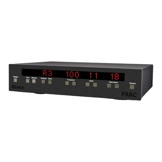
PARC
Operator's Manual
Thank you for purchasing the PARC, Parametric Adaptive Room Compensation, System. As you are already
well aware, high end audio systems and even mid-fi systems have reached a level that exceeds the
performance of the room they are in. All of Rives Audio products and services are designed to compensate
these room anomalies and provide the listener with a more rewarding listening experience.
The PARC was developed by engineers with years of experience in high end professional mixing boards. It is
these parametric compensation systems that are employed in the PARC. All of the components are the finest
available. All of the signal paths are as short as possible. All power supplies are quiet, reliable, and built
beyond the needs of the system. All display and control electronics are isolated as much as possible from the
signal path. The result is a system that can enhance even the finest high end system.
The PARC also uses a software control system. This allows for easy upgrading of the software. Over time we
may find ways of enhancing the product and this architecture will allow the user to upgrade the software very
easily.
Topics:
© Copyright 2002 Rives Audio, Inc.
Page
2
4
5
8
9
10
11
12
13
13
Page
1
Advertisement
Table of Contents

Summary of Contents for Rives Audio PARC
-
Page 1: Table Of Contents
The result is a system that can enhance even the finest high end system. The PARC also uses a software control system. This allows for easy upgrading of the software. Over time we may find ways of enhancing the product and this architecture will allow the user to upgrade the software very easily. -
Page 2: Connections
PARC between the two. When connecting the PARC via a pre-amp and amp, connect the line in on the PARC to the outputs on the pre-amp. Then connect the line out on the PARC to the inputs on the amplifier. Below is an example of the PARC connected via the XLR (balanced connectors). - Page 3 Operator’s Manual When connecting the PARC via a tape loop, connect the line in on the PARC to the tape record outs on the receiver or pre-amp. Then connect the line out on the PARC to the tape in on the receiver or pre-amp. The example shown below is with single ended inputs, which is the most likely to be used with a tape loop.
-
Page 4: Basic Function
The PARC operates between 16 and 350 Hz. It attenuates ONLY, there is no gain in the PARC. The purpose is to reduce the frequencies caused by room excitation. There are three bands per channel. These three bands were originally designed to compensate for the 3 parallel surfaces in most rectangular rooms (side to side, front to back, and floor to ceiling). -
Page 5: Set-Up
PARC will only compensate for frequencies below 512 Hz. The first step in setting up the PARC is measuring the room and loudspeaker response. Placement of the meter is important. It should be placed at the typical listener position. If you have a tripod, this is the best way to insure a stable an accurate placement of the meter. - Page 6 -3db point from the peak. If you want to calculate the Q just extrapolate the line to 3 dB below the peak and calculate the width there. These settings should be written down, so that they can then be saved to the PARC. Left Channel, Band 1:...
- Page 7 The red light should turn off, and there should be a complete set of readings in the panel. We recommend that you leave the display off unless you are setting up the PARC. When the display is off, all keys, except the bypass, are not functional.
-
Page 8: Memory
Now that both channels have been set up, it’s time to save this to memory. There are 3 memories. While the PARC is primarily designed to be left in one particular compensation mode, the memory settings allow the user flexibility to tailor the sound for particular situations. We recommend that the flattest response be set to memory 1 and then tailored responses set to memory 2 and 3. -
Page 9: Troubleshooting
I can’t go above 350 Hz Frequency: This is normal operation. The unit only functions between 16 and 350 Hz. The BARE is not communicating with the PARC: Please see the BARE manual for this. There is a communications troubleshooting protocol built into the software. -
Page 10: Appendix Aspl Meter Correction
8000 10000 12500 16000 20000 Compensation Numbers Copyrighted by Granite Audio, with all rights reserved, and used here with their kind permission. These numbers also verified by our own extensive in-house testing. Page 10 © Copyright 2002 Rives Audio, Inc. -
Page 11: Appendix B Q Factor And Frequency Comparison
Q factor to the octaves remains constant, while the width in Hertz changes with varying center frequencies. The PARC is set up with constant Q factor circuitry. It is for this reason that the width is expressed in terms of Q factors. -
Page 12: Appendix C Chart For Plotting Loudspeaker And Room Response
Operator’s Manual Appendix C: Frequency Chart for plotting loudspeaker and room response This chart is best used with the Rives Audio Test CD and a Radio Shack SPL analog meter. You may download additional copies of this chart at http://www.rivesaudio.com/files/freqchrt.PDF Page 12 ©... -
Page 13: Specifications
Attenuation Level: 0 to 18 dB, independent per band and channel Contact Information: Rives Audio The ATI Group, Ste A-1 8301 Patuxent Range Road Jessup, MD 20794 Phone 800-959-6553 www.rivesaudio.com for Service and Warranty contact: service@rivesaudio.com © Copyright 2002 Rives Audio, Inc. Page...
Need help?
Do you have a question about the PARC and is the answer not in the manual?
Questions and answers