Table of Contents
Advertisement
Advertisement
Table of Contents

Summary of Contents for JR Sport S400
- Page 1 4-CHANNEL FM RADIO SYSTEM INSTRUCTION MANUAL MANUFACTURED BY JR REMOTE CONTROL...
-
Page 3: Table Of Contents
4.1 Receiver Features ..... . . 4 11.1 S400 Trainer System....12 4.2 Receiver Specifications . -
Page 4: System Specifications
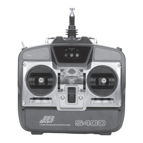
• Adjustable control stick length (page 5) • 9.6V 600mAh NiCad transmitter battery pack • Trainer system feature compatible with all * (not included with UL version) current JR and JR Sport radio systems • Power output approximately 750mw TRANSMITTER LAYOUT Transmitter LED Battery... -
Page 5: Transmitter Specifications
There is an eye hook on the front of the transmitter so that the transmitter will be perfectly balanced for attaching an optional neck strap (JRPA023). The when a neck strap is used. eye hook is precisely positioned (see Section 3.2) S400 MANUAL... -
Page 6: Rs600 Receiver
1 oz. Size (W x L x H) Size (W x L x H) 1.43" x 2.06" x .55" 1.38" x 0.75" x 0.50" Receiver Antenna Receiver Antenna 39" for all Aircraft 39" for all Aircraft Frequencies Frequencies S400 MANUAL... -
Page 7: St47 Servo
.08 sec/60° 3-Pole Ferrite (sec./60°) Weight 6 grams (oz.) 6. AIRBORNE (RECEIVER) BATTERY PACK (NOT INCLUDED WITH UL SYSTEM) Model Number JSPB700 Size 2.24" x .59" x 2.05" (WxLxH) Voltage Weight 1.2V x 4 NiCad (4.8V 700mAh) (oz.) S400 MANUAL... -
Page 8: Charger Specifications
Red to Negative negative polarity, otherwise damage will occur to the charge circuit of the S400. The JR Sport warranty Charger Pigtail for Receiver does not cover any system that is damaged by reverse polarity charging. -
Page 9: Pre-Installation System Preparation
9. PRE-INSTALLATION SYSTEM PREPARATION FLIGHT PACK CONNECTIONS Connect all flight pack components of your S400 System as outlined in the diagram below: RECEIVER BATTERY B700 Not Used With 4-Channel System Optional FLAP Not Used With Optional 4-Channel System GEAR ON/OFF SWITCH HARNESS... -
Page 10: St47 Servo Preparation
Servo Eyelet Figure 2 Servo Lead w/Connector SYSTEM CHECK Slide the power ON/OFF switch on your S400 By moving each of the two transmitter sticks in Transmitter to the “ON” position. a fore-aft, left-right motion, the corresponding throttle, rudder, elevator, and aileron (optional) Next, slide the ON/OFF switch on your flight pack servo arm/wheel will rotate. -
Page 11: Flight Pack Installation
The flange of the brass eyelets should face down (toward the wood). See Section 9.3. Servo Horn 90° with Servo at Control Rod Neutral/Center Position S400 MANUAL... -
Page 12: Servo Reversing
Up Elevator Up Elevator Throttle Aileron Elevator Rudder (Mode II Transmitter Shown) Servo Reversing Switches (Located behind Transmitter Battery Pack) High (Full) Rudder Aileron Down Aileron Up Carburetor Elevator Low (Idle) 1/16" Up Elevator Throttle Right Aileron Right Rudder S400 MANUAL... -
Page 13: Adjusting Control Surface Travel
Quite simply, by moving the control rod in on the original servo horn screw. servo arm/wheel, control surface travel will be S400 MANUAL... -
Page 14: Pre-Flight Information
JR radios that have built-in trainer systems. An transmitter can be used as either a master (trainer) optional trainer cord is needed (JRPA130). or as a slave (trainee). The S400 is compatible with all other current PPM selectable (FM) JR Sport Trainer Switch... -
Page 15: General Notes
6. Check to be sure that all servo pigtails and properly secured. switch harness plugs are secure in the receiver. 3. Ensure that all surfaces are moving in the Also, make sure that the switch harness moves proper manner. completely in both directions. S400 MANUAL... -
Page 16: Warranty And Service Information
Mail your system to: shipping. Horizon Service Center 4105 Fieldstone Road 4. Include detailed information explaining your Champaign, Illinois 61822 operation of the equipment and problem(s) (217) 355-9511 encountered. Provide an itemized list of equipment enclosed and identify any particular S400 MANUAL... -
Page 17: Frequency Chart
15. FREQUENCY CHART 72MHz requires no special license to operate. * It is important that you attach the enclosed frequency ID plates/flag to your S400 transmitter antenna. 72MHz 72MHz CH.NO. FREQUENCY CH.NO. FREQUENCY 72.090 72.550 72.110 72.570 72.130 72.590 72.150 72.610... -
Page 18: Notes On The Included Receivers
(+) shift operation and towards the servo wire in/out end of the negative (-) shift operation. receiver. Lift that tab slightly while pulling on the PC board gently. S400 MANUAL... -
Page 19: Information Regarding The Rs6Ul Receiver
(motor, speed controller, servos, etc.) as possible. Please contact the Horizon Service Center for further instructions. Note: Under no circumstances should the length of the receiver antenna be altered, as this will directly affect the tuning and overall range of the receiver. S400 MANUAL... - Page 20 MANUFACTURED BY JR REMOTE CONTROL DISTRIBUTED EXCLUSIVELY BY HORIZON HOBBY, INC. CHAMPAIGN, IL 61822 horizonhobby.com © 2005 7409...
Need help?
Do you have a question about the S400 and is the answer not in the manual?
Questions and answers